element14 Community
element14 Community
    Register Log In
  • Site
  • Search
  • Log In Register
  • About Us
  • Community Hub
    Community Hub
    • What's New on element14
    • Feedback and Support
    • Benefits of Membership
    • Personal Blogs
    • Members Area
    • Achievement Levels
  • Learn
    Learn
    • Ask an Expert
    • eBooks
    • element14 presents
    • Learning Center
    • Tech Spotlight
    • STEM Academy
    • Webinars, Training and Events
    • Learning Groups
  • Technologies
    Technologies
    • 3D Printing
    • FPGA
    • Industrial Automation
    • Internet of Things
    • Power & Energy
    • Sensors
    • Technology Groups
  • Challenges & Projects
    Challenges & Projects
    • Design Challenges
    • element14 presents Projects
    • Project14
    • Arduino Projects
    • Raspberry Pi Projects
    • Project Groups
  • Products
    Products
    • Arduino
    • Avnet Boards Community
    • Dev Tools
    • Manufacturers
    • Multicomp Pro
    • Product Groups
    • Raspberry Pi
    • RoadTests & Reviews
  • Store
    Store
    • Visit Your Store
    • Choose another store...
      • Europe
      •  Austria (German)
      •  Belgium (Dutch, French)
      •  Bulgaria (Bulgarian)
      •  Czech Republic (Czech)
      •  Denmark (Danish)
      •  Estonia (Estonian)
      •  Finland (Finnish)
      •  France (French)
      •  Germany (German)
      •  Hungary (Hungarian)
      •  Ireland
      •  Israel
      •  Italy (Italian)
      •  Latvia (Latvian)
      •  
      •  Lithuania (Lithuanian)
      •  Netherlands (Dutch)
      •  Norway (Norwegian)
      •  Poland (Polish)
      •  Portugal (Portuguese)
      •  Romania (Romanian)
      •  Russia (Russian)
      •  Slovakia (Slovak)
      •  Slovenia (Slovenian)
      •  Spain (Spanish)
      •  Sweden (Swedish)
      •  Switzerland(German, French)
      •  Turkey (Turkish)
      •  United Kingdom
      • Asia Pacific
      •  Australia
      •  China
      •  Hong Kong
      •  India
      •  Korea (Korean)
      •  Malaysia
      •  New Zealand
      •  Philippines
      •  Singapore
      •  Taiwan
      •  Thailand (Thai)
      • Americas
      •  Brazil (Portuguese)
      •  Canada
      •  Mexico (Spanish)
      •  United States
      Can't find the country/region you're looking for? Visit our export site or find a local distributor.
  • Translate
  • Profile
  • Settings
Raspberry Pi
  • Products
  • More
Raspberry Pi
Raspberry Pi Forum LED Driver Circut
  • Blog
  • Forum
  • Documents
  • Quiz
  • Events
  • Polls
  • Files
  • Members
  • Mentions
  • Sub-Groups
  • Tags
  • More
  • Cancel
  • New
Join Raspberry Pi to participate - click to join for free!
Featured Articles
Announcing Pi
Technical Specifications
Raspberry Pi FAQs
Win a Pi
Raspberry Pi Wishlist
Actions
  • Share
  • More
  • Cancel
Forum Thread Details
  • Replies 24 replies
  • Subscribers 653 subscribers
  • Views 3149 views
  • Users 0 members are here
Related

LED Driver Circut

fskrzycki
fskrzycki over 1 year ago

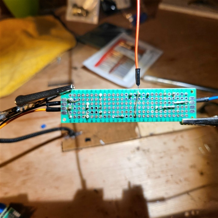
Can you review this circuit layout. Using Rasp pi to drive a high end LED strip. 24v mini 0402 LED.

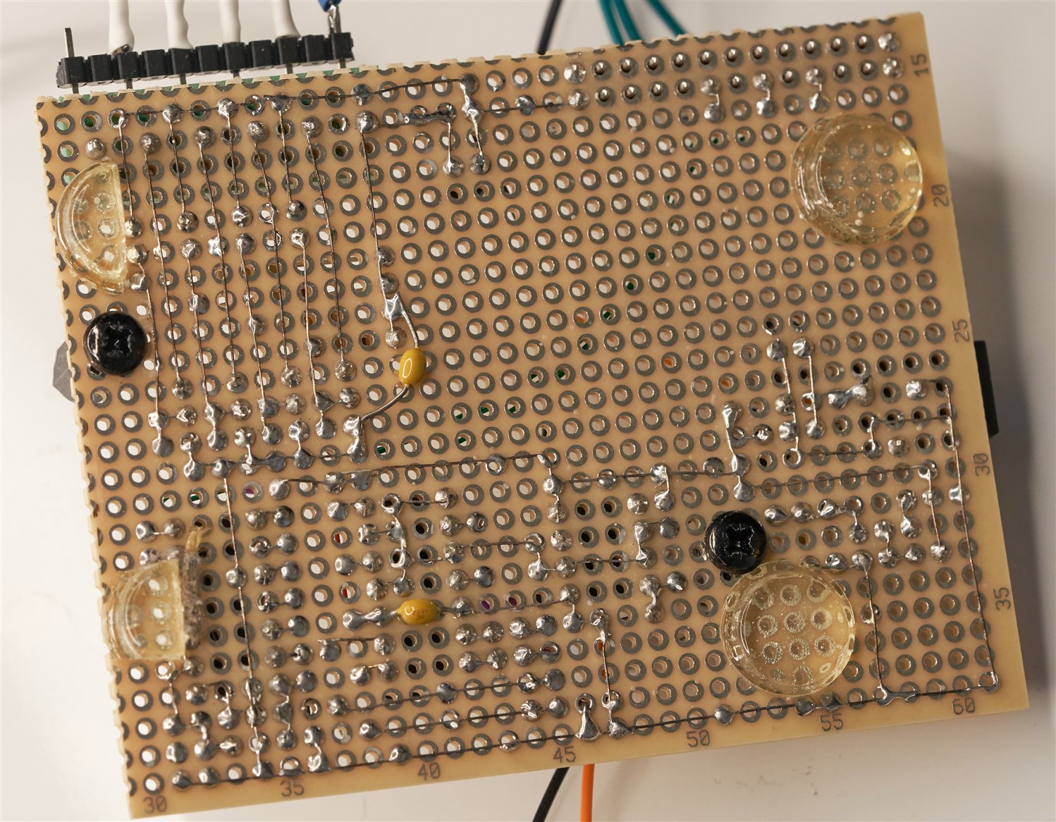
I am experiencing a power leak on the board i built. I believe i need  resistance after my optocoupler on the Pi. side.

With the high voltage I am looking to protect the pi while still safely operating the strip. 

i have changed 2 things on this board since the picture.  I now have all grounds on ths Zenner Diode side connected to power supply ground and I decreased the Resistor from. 100k to 10k on the advise of Open Ai

image

image

image

  • Sign in to reply
  • Cancel
Parents
  • strb
    strb over 1 year ago

    Looking at PC817 datasheet it has a minimum current transfer ratio of 50%. From the scheme I see that with 0V on the mosfet gate the collector current of the transistor (PC817output) is about 9mA -> this means that the diode needs 18mA on worst case to be able to handle such output current! With 220Ohm series resistor however you're polarizing it with only 2mA, it has no chance to handle all the output current.

    If you keep your 100k resistor and swap the 1k with 10k resistor the current that the optocoupler has to handle drops to about 1mA and should work (given that all other components are fine and not damaged by ESD as pointed out by others Slight smile )

    Beware that swapping 1k with 10k will slow down turn on transient, but I don't think it will be an issue...

    • Cancel
    • Vote Up 0 Vote Down
    • Sign in to reply
    • Cancel
Reply
  • strb
    strb over 1 year ago

    Looking at PC817 datasheet it has a minimum current transfer ratio of 50%. From the scheme I see that with 0V on the mosfet gate the collector current of the transistor (PC817output) is about 9mA -> this means that the diode needs 18mA on worst case to be able to handle such output current! With 220Ohm series resistor however you're polarizing it with only 2mA, it has no chance to handle all the output current.

    If you keep your 100k resistor and swap the 1k with 10k resistor the current that the optocoupler has to handle drops to about 1mA and should work (given that all other components are fine and not damaged by ESD as pointed out by others Slight smile )

    Beware that swapping 1k with 10k will slow down turn on transient, but I don't think it will be an issue...

    • Cancel
    • Vote Up 0 Vote Down
    • Sign in to reply
    • Cancel
Children
  • fskrzycki
    fskrzycki over 1 year ago in reply to strb

    thx. ill report back

    • Cancel
    • Vote Up 0 Vote Down
    • Sign in to reply
    • Cancel
  • shabaz
    shabaz over 1 year ago in reply to strb

    I think your calculation has an error - there should be just over 8 mA through the optocoupler LED, not 2 mA. (3.3 - 1.4) / 220  = 8.6 mA.

    So it's nowhere near as bad as you mention.

    8 mA is a bit of a compromise, because it depends on how many connections there are on the Pi, since there's an overall limit. However, I guesstimated that 8 mA should be harmless. 

    It's not a production circuit, I don't think it needs to be guaranteed to function for the worst case conditions, since CTR of 50% is very untypical.  

    Having said that, for sure the component values can be adjusted. But I don't think from the symptom, that this is the issue. But it can be known 100% by simply shorting the 100k resistor. 

    • Cancel
    • Vote Up 0 Vote Down
    • Sign in to reply
    • Cancel
  • strb
    strb over 1 year ago in reply to shabaz

    Oh, you're right, I messed up the calculation. My bad, my statement is wrong! With 8mA of led drive it should work indeed 

    • Cancel
    • Vote Up +1 Vote Down
    • Sign in to reply
    • Cancel
  • fskrzycki
    fskrzycki over 1 year ago in reply to strb

    I put the original circuit on a breadboard and it works using pwm commands. MOSFETS are fine.. No leakage. (no sparkslStuck out tongue winking eye). I'm thinking I should use a bigger perforated board to separate the components further away.  the boards are such crap, any suggestions on that.

    Separate question. I will be using a start up service to activate the Py led driver,  I will use "try", "while true", and "except KeyboardInterrupt" to put my driver in a loop. there will be no keyboard connected.. will that be an issue? also can i add an "if" statement that will acknowledged input from a button? 

    • Cancel
    • Vote Up +1 Vote Down
    • Sign in to reply
    • Cancel
  • dang74
    dang74 over 1 year ago in reply to fskrzycki

    Read the comments posted by Scottiebabe about a possible wiring error and inconsistency between schematic and protoboard wiring.

    • Cancel
    • Vote Up +1 Vote Down
    • Sign in to reply
    • Cancel
  • shabaz
    shabaz over 1 year ago in reply to fskrzycki

    Perfboard is about as decent a prototyping solution as there is, before moving to a full printed circuit board. 

    Having said that, there is some slightly nicer perfboard than the low-cost Amazon ones. I like this one: https://www.newark.com/roth-elektronik/re200-c3/prototyping-brd-eurocard-100-2x160/dp/05M1075?ost=re200-c3 it's a decent price, and  is a large size (160 x 100mm) easy to break into a smaller piece if required, and the pads are not too large, which is occasionally helpful, plus quick to desolder and re-work, since the pads are not through-hole plated (the green board in your photo is through-hole plated which is inherently more robust, but non-through hole boards can be reliable too).

    A custom PCB is low-cost, and would be worth trying, although there's a learning curve (but not much; a week of tutorials/practice for a couple of hours each day would be enough to learn say KiCad https://www.kicad.org/ ; I can recommend a video if you wish to go that route).

    • Cancel
    • Vote Up +2 Vote Down
    • Sign in to reply
    • Cancel
  • shabaz
    shabaz over 1 year ago in reply to fskrzycki

    Just remembered I did a project with a Pi involving 24V lights in the past too, using perfboard, it is documented here:  Raspberry Pi enabled Christmas Lights   .

    However mine was lower power (about 2.8W per chain of lights, and there were 4 chains), and it used lamps instead of LEDs. It definitely helps using a larger board. This was 85 x 70 mm approx:

    image

    Underside, using thin (30 AWG) bare wire, but it's possible to use solderable enamel wire etc. I used the perfboard mentioned above.

    image

    However now PCBs are so cheap, if I were to do it again, I'd make a custom board.

    • Cancel
    • Vote Up +1 Vote Down
    • Sign in to reply
    • Cancel
  • scottiebabe
    scottiebabe over 1 year ago in reply to dang74

    lol in that photographed circuit above when the opto is switched off,  the FET's gate voltage is determined by in-circuit leakage currents...

    • Cancel
    • Vote Up 0 Vote Down
    • Sign in to reply
    • Cancel
  • fskrzycki
    fskrzycki over 1 year ago in reply to dang74

    i caught the mistake two nights ago when i was checking the Msft for connection problems to the 100k. i spent some time remaking a new circuit with care to insulate everything, even after cleaning the board with rubbing alcohol, but when i was finished, it still didn't operate correctly. my continuity was off all over the board. i had pin holes with no surrounding components giving charge. 

    • Cancel
    • Vote Up 0 Vote Down
    • Sign in to reply
    • Cancel
  • fskrzycki
    fskrzycki over 1 year ago in reply to shabaz

    looks good, the boards i have now are traceable on both sides. My plan was to connect all three and run grounds together and power together. I ruined my week by losing my galvanic isolation Stuck out tongue

    • Cancel
    • Vote Up 0 Vote Down
    • Sign in to reply
    • Cancel
element14 Community

element14 is the first online community specifically for engineers. Connect with your peers and get expert answers to your questions.

  • Members
  • Learn
  • Technologies
  • Challenges & Projects
  • Products
  • Store
  • About Us
  • Feedback & Support
  • FAQs
  • Terms of Use
  • Privacy Policy
  • Legal and Copyright Notices
  • Sitemap
  • Cookies

An Avnet Company © 2025 Premier Farnell Limited. All Rights Reserved.

Premier Farnell Ltd, registered in England and Wales (no 00876412), registered office: Farnell House, Forge Lane, Leeds LS12 2NE.

ICP 备案号 10220084.

Follow element14

  • X
  • Facebook
  • linkedin
  • YouTube