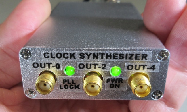
Unbeknownst to the reader, this project is actually a $4 piece of junk. At a casual glance, you may be tempted to believe it is boutique product.
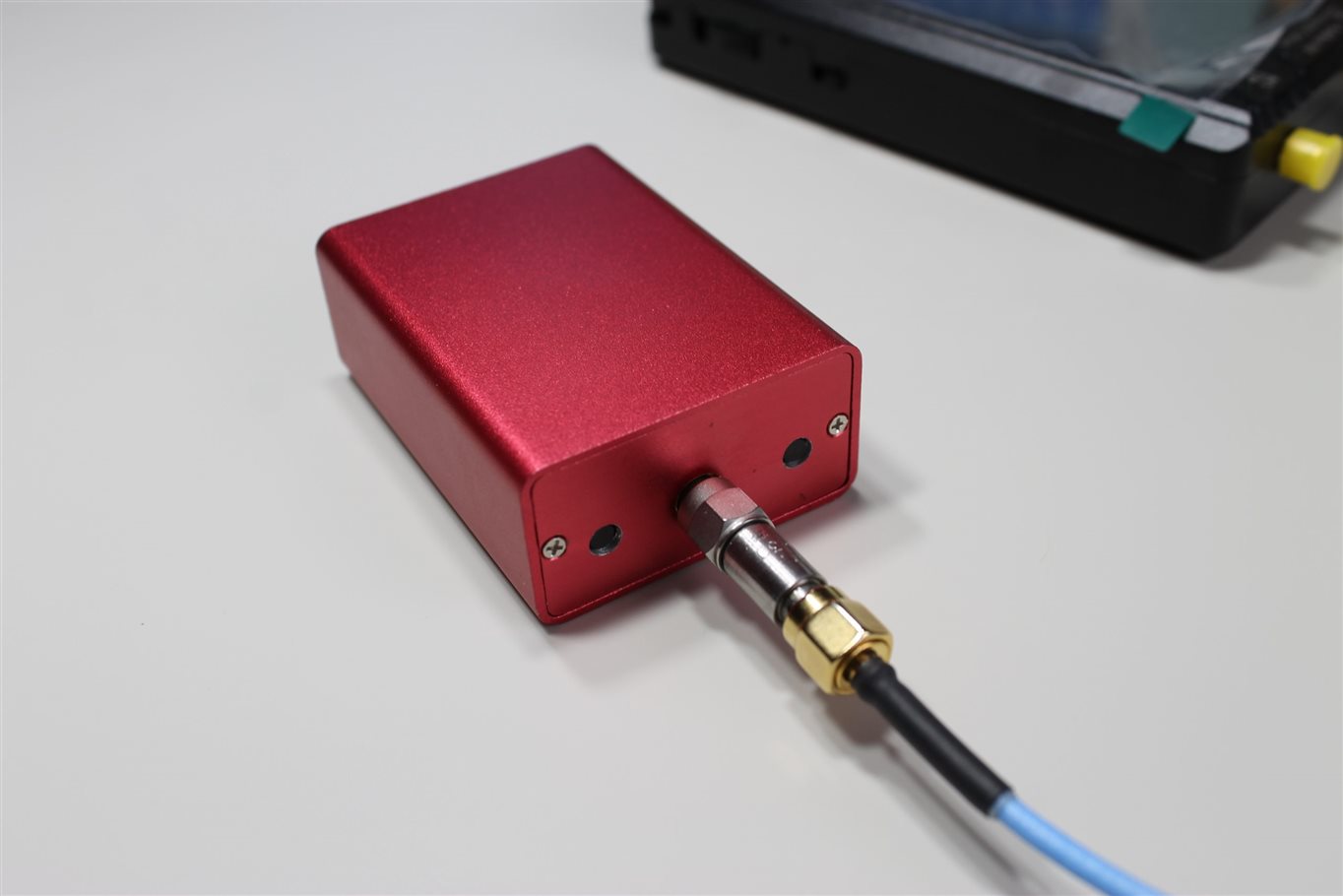
Ooh ahh, fancy. I purchased one of these extruded aluminum enclosure from a local seller.

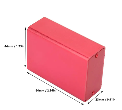
Photos curtesy of this product listing: https://www.aliexpress.com/item/33053448840.html
I cut 2 pieces of bare copper clad board to fit within the PCB mounting channels of the enclosure.
I used my Dremel to drill 4 mounting holes aligned to 4 ground pins on the edge connectors of the Pico.
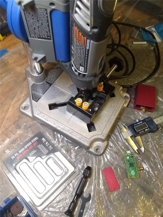
I don’t use the drill press stand attachment to my Dremel enough to have a strong opinion about it. There are fancier model making precision drill presses, but I already have this so I use it.
The Pico soldered to a carrier card

To machine out the microUSB connector slot, I first a put a piece of blue tape on the enclosure endplate and made an impression of the connector.

I then drilled and filled the slot large enough such that the USB connector could slide right through.
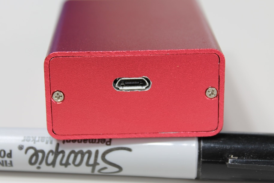
Not perfect, but close enough for my standards.
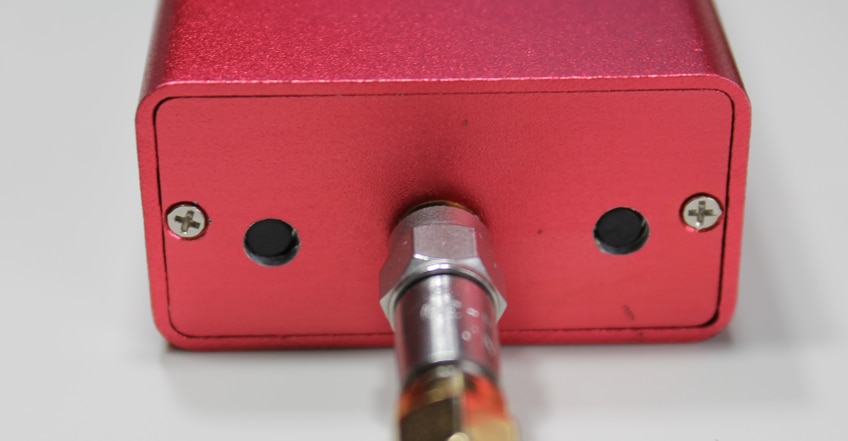
Similar process for the SMA connectors.
The 2 pushbuttons were a very long and tedious process. I drilled the holes first and then tried to solder the buttons to match the holes. I used what I had at hand, but this process could be avoided entirely using proper pushbutton and a custom PCB. But, in the end I got it to fit together fairly well.
The second prototype card
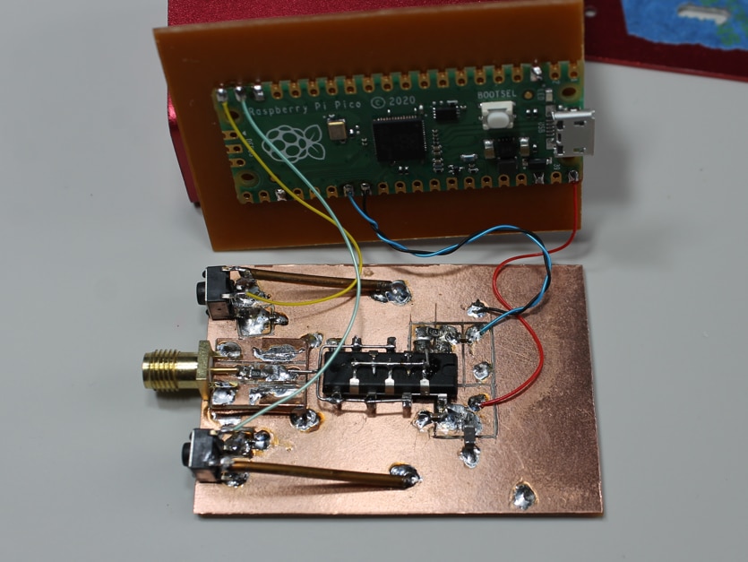
It is just an amplifier/buffer using a screaming fast hex logic inverter.
In the end I have a little CW signal generator capable of tuning from DC to 200 MHz and provides an output power of ~13.5 dBm into 50 Ohms.
Conclusion
The end result looks fabulous on the exterior.
Locating and machining the cutouts for the USB connector and SMA connector were relatively easy.
There is ample room for prototype style construction and a RPI Pico.
Using this style of enclosure is a lot more work as apposed to loosely tossing everything in a box and using panel mount connectors and interface elements. Wherever you drilled the hole, is where the connector ends up.
If your going to go to the trouble of making a custom PCB, you could make a printable drill template for the endplates. Or spend even more and order custom endplates using a PCB or aluminum.
Happy tinkering!


