element14 Community
element14 Community
    Register Log In
  • Site
  • Search
  • Log In Register
  • About Us
  • Community Hub
    Community Hub
    • What's New on element14
    • Feedback and Support
    • Benefits of Membership
    • Personal Blogs
    • Members Area
    • Achievement Levels
  • Learn
    Learn
    • Ask an Expert
    • eBooks
    • element14 presents
    • Learning Center
    • Tech Spotlight
    • STEM Academy
    • Webinars, Training and Events
    • Learning Groups
  • Technologies
    Technologies
    • 3D Printing
    • FPGA
    • Industrial Automation
    • Internet of Things
    • Power & Energy
    • Sensors
    • Technology Groups
  • Challenges & Projects
    Challenges & Projects
    • Design Challenges
    • element14 presents Projects
    • Project14
    • Arduino Projects
    • Raspberry Pi Projects
    • Project Groups
  • Products
    Products
    • Arduino
    • Avnet Boards Community
    • Dev Tools
    • Manufacturers
    • Multicomp Pro
    • Product Groups
    • Raspberry Pi
    • RoadTests & Reviews
  • Store
    Store
    • Visit Your Store
    • Choose another store...
      • Europe
      •  Austria (German)
      •  Belgium (Dutch, French)
      •  Bulgaria (Bulgarian)
      •  Czech Republic (Czech)
      •  Denmark (Danish)
      •  Estonia (Estonian)
      •  Finland (Finnish)
      •  France (French)
      •  Germany (German)
      •  Hungary (Hungarian)
      •  Ireland
      •  Israel
      •  Italy (Italian)
      •  Latvia (Latvian)
      •  
      •  Lithuania (Lithuanian)
      •  Netherlands (Dutch)
      •  Norway (Norwegian)
      •  Poland (Polish)
      •  Portugal (Portuguese)
      •  Romania (Romanian)
      •  Russia (Russian)
      •  Slovakia (Slovak)
      •  Slovenia (Slovenian)
      •  Spain (Spanish)
      •  Sweden (Swedish)
      •  Switzerland(German, French)
      •  Turkey (Turkish)
      •  United Kingdom
      • Asia Pacific
      •  Australia
      •  China
      •  Hong Kong
      •  India
      •  Korea (Korean)
      •  Malaysia
      •  New Zealand
      •  Philippines
      •  Singapore
      •  Taiwan
      •  Thailand (Thai)
      • Americas
      •  Brazil (Portuguese)
      •  Canada
      •  Mexico (Spanish)
      •  United States
      Can't find the country/region you're looking for? Visit our export site or find a local distributor.
  • Translate
  • Profile
  • Settings
Raspberry Pi
  • Products
  • More
Raspberry Pi
Raspberry Pi Forum Interfacing Raspberry Pi 5G HAT with other controller
  • Blog
  • Forum
  • Documents
  • Quiz
  • Events
  • Polls
  • Files
  • Members
  • Mentions
  • Sub-Groups
  • Tags
  • More
  • Cancel
  • New
Join Raspberry Pi to participate - click to join for free!
Featured Articles
Announcing Pi
Technical Specifications
Raspberry Pi FAQs
Win a Pi
Raspberry Pi Wishlist
Actions
  • Share
  • More
  • Cancel
Forum Thread Details
  • State Suggested Answer
  • Replies 33 replies
  • Answers 1 answer
  • Subscribers 658 subscribers
  • Views 4083 views
  • Users 0 members are here
Related

Interfacing Raspberry Pi 5G HAT with other controller

meera_hussien
meera_hussien over 1 year ago

Gooday,

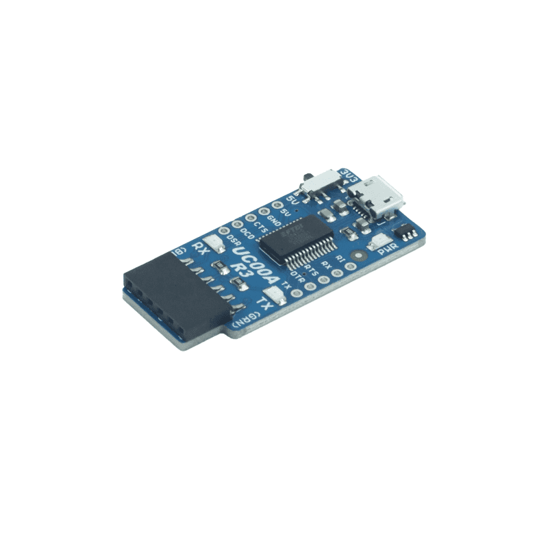
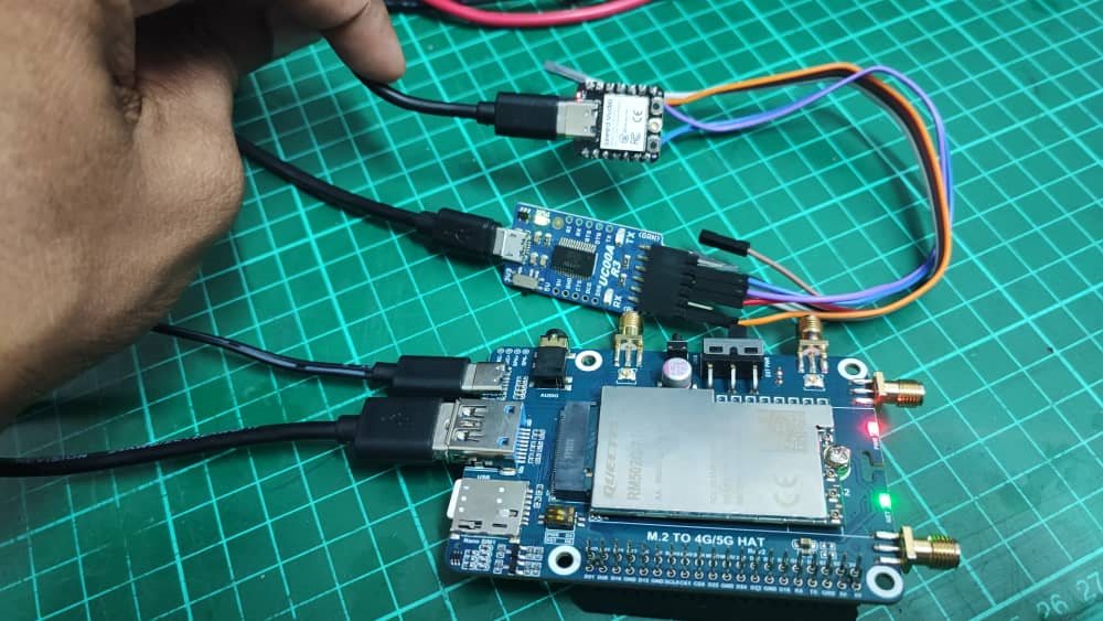
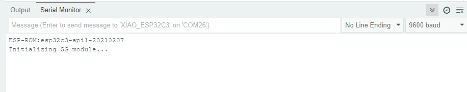
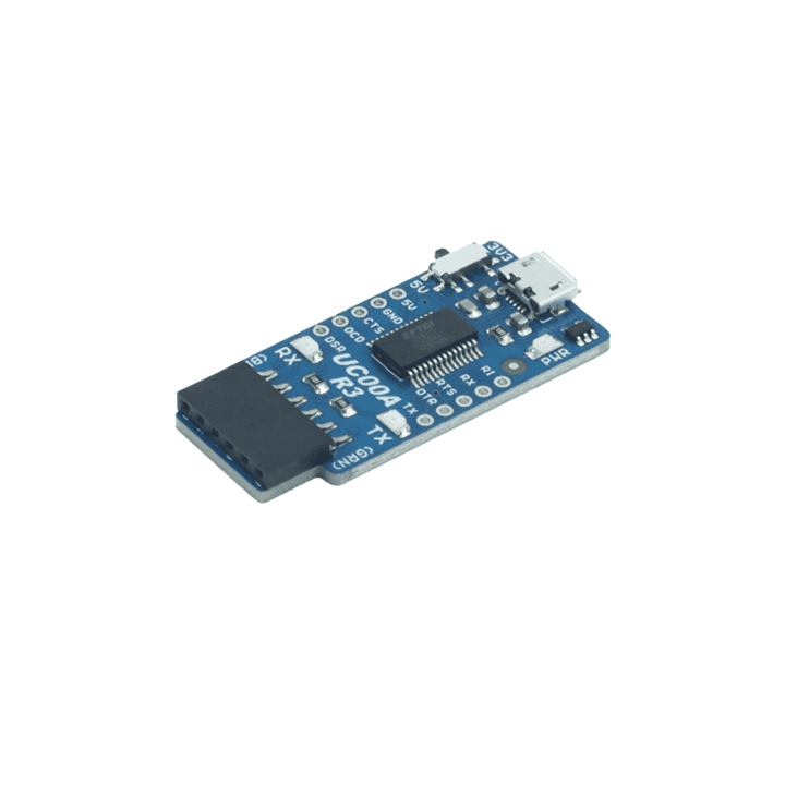
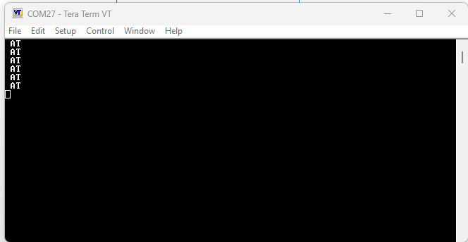
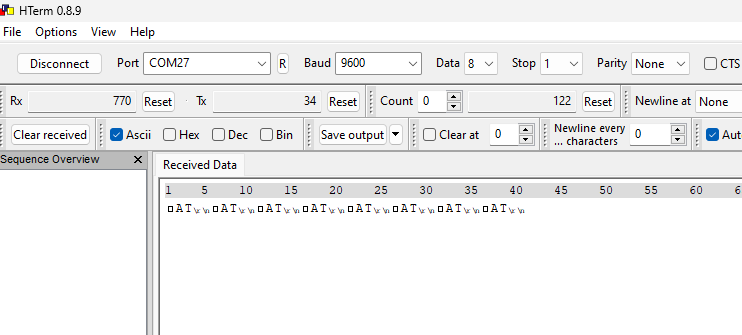
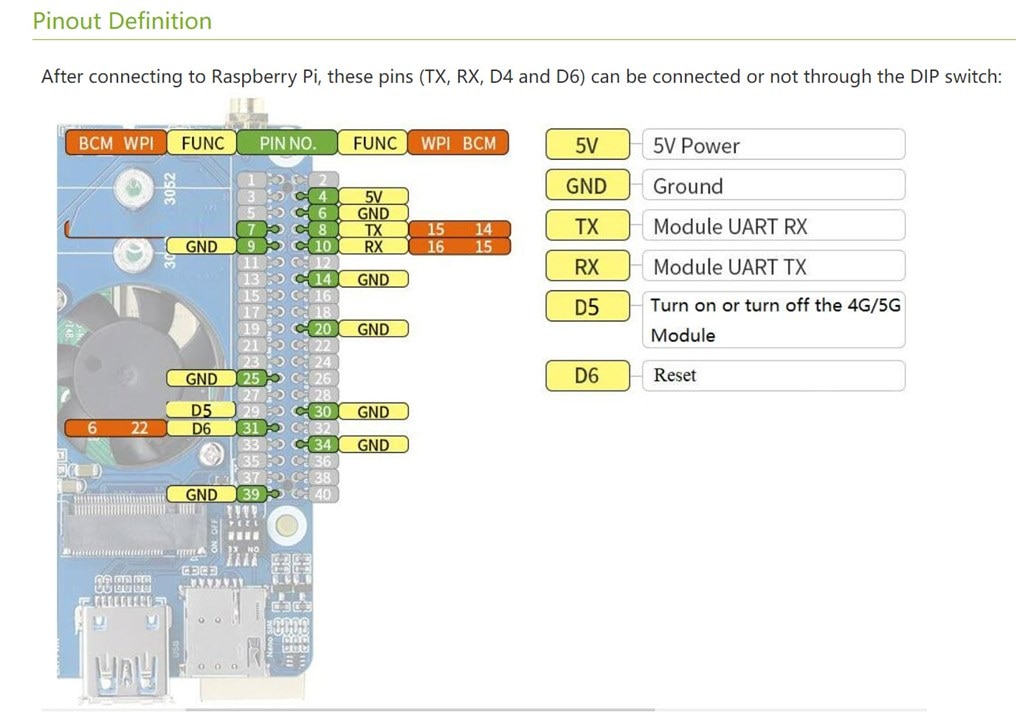
I am trying to interface the 5G HAT module with the XIAO ESP32C3 module through the UART and also through the USB to TTL, but both are unsuccessful. 

Has anyone tried this method? Or is there a different method that can be used?

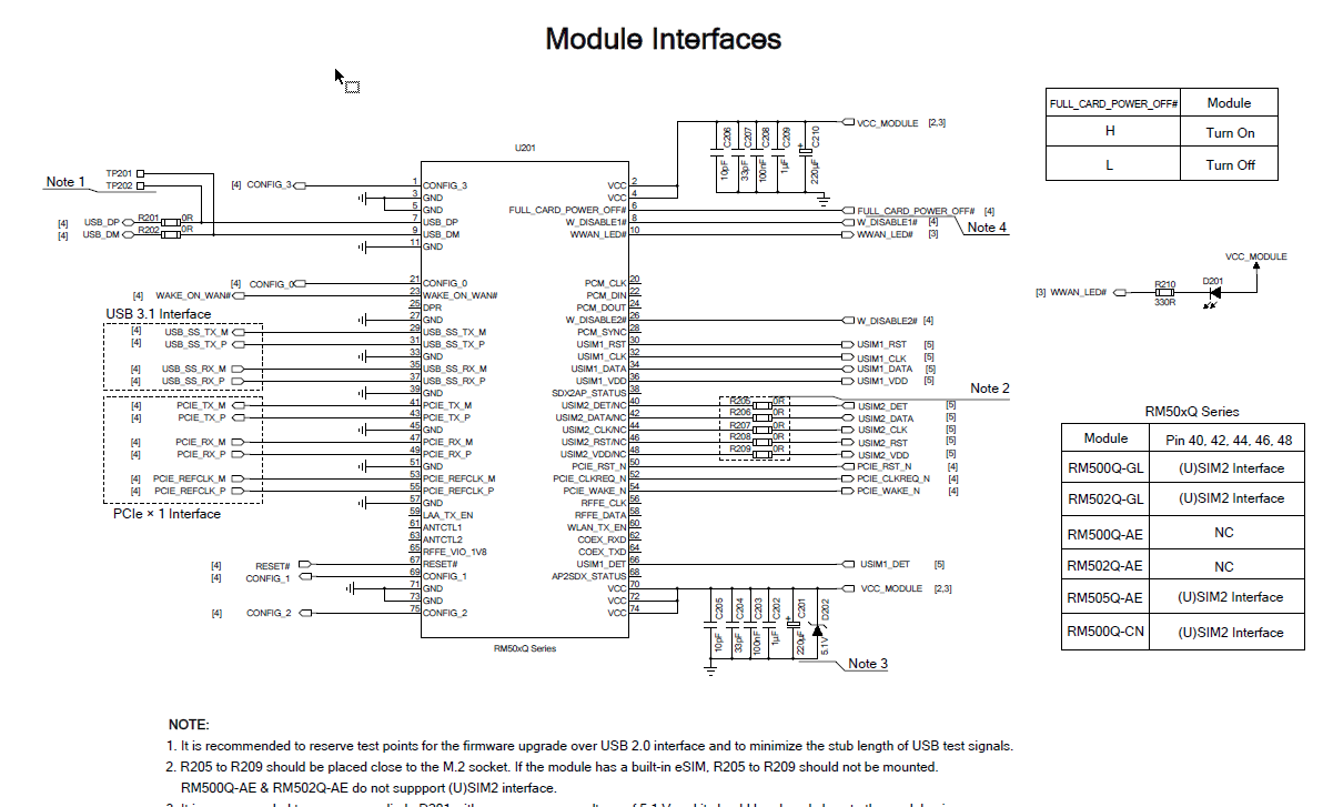
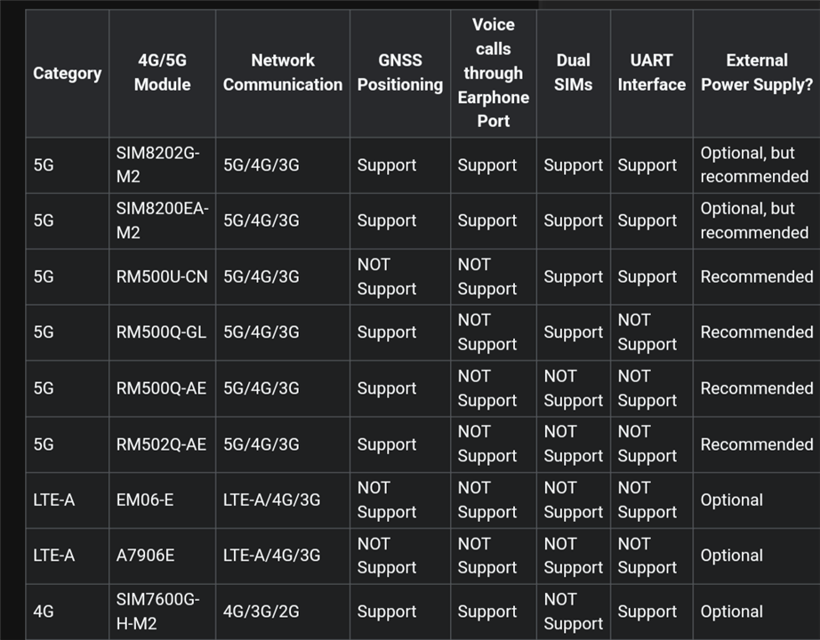
Below is the 5G HAT that i am using 

image

https://www.waveshare.com/wiki/RM500Q-GL_5G_HAT.

Appreciate if anyone can help on this

  • Sign in to reply
  • Cancel
Parents
  • shabaz
    0 shabaz over 1 year ago

    Hi Meera,

    I've not used that particular Pi HAT, but I have used another WaveShare Pi HAT (for 4G/LTE), and the easiest way to interface was to use the on-board USB-UART. I too didn't use Pi. I see your board also has a USB connector, although it's weird that it is a USB Type-A connector. Mine had a micro USB connector.

    Waveshare has put the USB connector specifically for testing out using the UART, so if that doesn't work, then that needs to be resolved first. 

    For the HAT board I used, I could see in Windows a "SimTech" device appear under Other Devices, and I could connect to it from a serial terminal (PuTTY etc). Then you can use the command manual to see what AT commands are available.

    • Cancel
    • Vote Up +1 Vote Down
    • Sign in to reply
    • Verify Answer
    • Cancel
  • meera_hussien
    0 meera_hussien over 1 year ago in reply to shabaz

    Thanks for the info shabaz . To use the on-board USB-UART, i can connect the USB UART to the microcontroller, right? Is there a specific model of USB-UART. For now i am using this model

    image

    https://my.cytron.io/p-uc00a-ftdi-usb-to-uart-converter?gad_source=1&gclid=CjwKCAjwx-CyBhAqEiwAeOcTdRxSOY-CX4LD6aRlMMRgviPsTpmzslS7RD6DMOrFXi9oXp66woBFOBoC4xAQAvD_BwE

    And i am using the code below for the handshake

    // Need this for the lower level access to set them up.
    #include <HardwareSerial.h>
    
    //Define two Serial devices mapped to the two internal UARTs
    HardwareSerial MySerial0(0);
    
    void setup()
    {
        // For the USB, just use Serial as normal:
        Serial.begin(115200);
    
        // Configure MySerial0 on pins TX=D6 and RX=D7 (-1, -1 means use the default)
        MySerial0.begin(115200, SERIAL_8N1, -1, -1);
       // MySerial0.print("MySerial0");
    //while(!Serial);
        Serial.println("Initializing 5G module...");
         Serial.println("Sending AT command...");
        MySerial0.write("AT\r");  
    // Send AT command to check communication
        delay(1000);
    
         // Check response from 5G module
        while (MySerial0.available()) {
            char c = MySerial0.read();
            Serial.print(c);
    
    
    }

    But somehow i am not getting any response from the 5G module. Below is the current setup.

    image

    The XIAO USB is connected to the PC. The RX and TX pin of the XIAO is connected to USB to UART converter. And the USB port on the UART is connected to the 5G module.

    • Cancel
    • Vote Up +1 Vote Down
    • Sign in to reply
    • Verify Answer
    • Cancel
  • meera_hussien
    0 meera_hussien over 1 year ago in reply to shabaz

    I will check on that pins and update you back if there is any progress. Thanks againshabaz . Really appreciate your help.Raised hands tone1

    • Cancel
    • Vote Up +2 Vote Down
    • Sign in to reply
    • Verify Answer
    • Cancel
  • meera_hussien
    0 meera_hussien over 1 year ago in reply to meera_hussien

    shabaz , just want to know if i were to use the UART to USB module instead of connecting directly to the UART pin on 40-way connecter, what changes do i need to make in the software or the hardware?

    Thank you in advance for the help.

    • Cancel
    • Vote Up 0 Vote Down
    • Sign in to reply
    • Verify Answer
    • Cancel
  • balajivan1995
    0 balajivan1995 over 1 year ago in reply to meera_hussien

    I believe I've the same LTE board Shabaz has mentioned. USB port in that board can be used to create multiple virtual ports including AT command port, diagnostic port, audio channel and GPS. If you have any microcontroller that has support USB for communication, you can enumerate the port, select the AT command port and exchange data over it. ESP32C3 doesn't support USB communication as far as I know, ESP32S3 does. The board I've has a dedicated USB to TTL section uses a CP2102 USB to TTL converter, so I assume if you use the same converter, it might work.

    • Cancel
    • Vote Up +2 Vote Down
    • Sign in to reply
    • Verify Answer
    • Cancel
  • shabaz
    0 shabaz over 1 year ago in reply to meera_hussien

    You'd need to have USB host capability on the microcontroller, which is less usual, and is another thing to troubleshoot, so it's not usually worth doing, especially since the microcontroller will already have a normal UART peripheral, so it's best to stick with that. 

    However, if you meant for testing on Windows, then personally I would not try to reuse that code, because you can test on Windows using a serial console (like PuTTY), or, automate with Python, because that will be far quicker to try out things, than using C. 

    For instance, you could write a Python function to open the serial port, and another Python function to write a string, and another to read from the serial port, and then you can on-the-fly issue the functions from the Python command line. Usually that's my preferred method of testing such types of things, using Python either from Windows, or from MicroPython (using a Pi Pico). 

    • Cancel
    • Vote Up +1 Vote Down
    • Sign in to reply
    • Verify Answer
    • Cancel
  • balajivan1995
    0 balajivan1995 over 1 year ago in reply to meera_hussien

    Can you please try the following snippet for sending AT command over the UART connection you've made here?

    char *at_check = "AT\r\n";

    MySerial0.printf("%s", at_check);

    //delay(1000); don't use delay here.

    while(MySerial0.available())

    {

    String at_response = MySerial0.readString();

    Serial.println(at_response);

    }

    • Cancel
    • Vote Up +1 Vote Down
    • Sign in to reply
    • Verify Answer
    • Cancel
  • balajivan1995
    0 balajivan1995 over 1 year ago in reply to balajivan1995

    Also, please check if it's possible change the hardware serial mapping to 1 instead of 0. I believe serial 0 is the default one you use for debugging.

    • Cancel
    • Vote Up 0 Vote Down
    • Sign in to reply
    • Verify Answer
    • Cancel
  • meera_hussien
    0 meera_hussien over 1 year ago in reply to shabaz

    shabaz , I am trying to communicate through the UART from the ESP32C3 directly with the UART pin on the 40 way connector. But somehow it got stuck here. 

    image

    And the code that i am using is 

    #include <HardwareSerial.h>
    #include <ArduinoJson.h>
    
    HardwareSerial mySerial(1);  
    // Using UART1
    
    
    const int RX_PIN = 9;  
    // Replace with actual RX pin number connected to 5G module
    const int TX_PIN = 10; 
    // Replace with actual TX pin number connected to 5G module
    
    void setup() {
        Serial.begin(9600);  
    // Initialize serial communication for debugging ni optional
    
        mySerial.begin(9600, SERIAL_8N1, RX_PIN, TX_PIN);  
    // Initialize UART1 for 5G module communication
    
        Serial.println("Initializing 5G module...");
        mySerial.write("AT\r\n");  
    
    
        // Check response from 5G module
        while (mySerial.available()) {
            char c = mySerial.read();
            Serial.println(c);  
    
     }
    
    void loop() {
    
    }
    

    And i have checked the D5 function. I noticed there is a onboard switch for it. I tested this code while putting the switch in the ON state as well as in the OFF state. The result are the same for both. 

    • Cancel
    • Vote Up +1 Vote Down
    • Sign in to reply
    • Verify Answer
    • Cancel
  • meera_hussien
    0 meera_hussien over 1 year ago in reply to balajivan1995

    Hi balajivan1995 . Thanks for the info. I dont have the CP2102 is in hand. But i tried using this USB to UART controller as in the image below. But it was unsuccessful either.

    image

    • Cancel
    • Vote Up 0 Vote Down
    • Sign in to reply
    • Verify Answer
    • Cancel
  • meera_hussien
    0 meera_hussien over 1 year ago in reply to balajivan1995

    I tried using the code above. Still getting the same result

    • Cancel
    • Vote Up 0 Vote Down
    • Sign in to reply
    • Verify Answer
    • Cancel
  • meera_hussien
    0 meera_hussien over 1 year ago in reply to balajivan1995

    I tried this as well, but it is still the same.

    • Cancel
    • Vote Up 0 Vote Down
    • Sign in to reply
    • Verify Answer
    • Cancel
Reply
  • meera_hussien
    0 meera_hussien over 1 year ago in reply to balajivan1995

    I tried this as well, but it is still the same.

    • Cancel
    • Vote Up 0 Vote Down
    • Sign in to reply
    • Verify Answer
    • Cancel
Children
  • balajivan1995
    0 balajivan1995 over 1 year ago in reply to meera_hussien

    1. Verify the data coming from ESP32 by connecting ESP32 Tx pin to Rx Pin of a TTL and use a putty/hterm to view the data from ESP32.

    2. As a next step, connect the Rx/Tx pins of TTL to 5G board, send the "AT\r\n" at different baud rates. My board has a default baudrate of 115200 and check for "OK" response.

    Once you verify these steps connect directly and run the code.

    • Cancel
    • Vote Up 0 Vote Down
    • Sign in to reply
    • Verify Answer
    • Cancel
  • balajivan1995
    0 balajivan1995 over 1 year ago in reply to balajivan1995

    Don't use Arduino IDE serial monitor. It'll abstract the "\r \n " characters. You need to use hterm which can show each and every byte that's being transmitted and received.

    • Cancel
    • Vote Up 0 Vote Down
    • Sign in to reply
    • Verify Answer
    • Cancel
  • meera_hussien
    0 meera_hussien over 1 year ago in reply to balajivan1995

    balajivan1995 , i connected the ESP32 with the TTL and can view the data that i am sending from from the ESP32. As shown in the image below

    image


    • Cancel
    • Vote Up 0 Vote Down
    • Sign in to reply
    • Verify Answer
    • Cancel
  • meera_hussien
    0 meera_hussien over 1 year ago in reply to meera_hussien

    i used the hterm and i get this result

    image

    Does this looks good?

    • Cancel
    • Vote Up 0 Vote Down
    • Sign in to reply
    • Verify Answer
    • Cancel
  • balajivan1995
    0 balajivan1995 over 1 year ago in reply to meera_hussien

    There is a garbage character that appears before  or after "AT\r\n", enable the checkbox of hex along with Ascii to see the unnecessary character and remove it from the code. Try to find out the reason for that, now connect the ttl to 5g modem and send the message like this. Make sure the "CR-LF" is selected under "Send on enter" dropdown option. It will automatically add "\r\n". If the modem returns OK, then you can connect ESP32 directly to Modem.

    image

    • Cancel
    • Vote Up 0 Vote Down
    • Sign in to reply
    • Verify Answer
    • Cancel
  • meera_hussien
    0 meera_hussien over 1 year ago in reply to balajivan1995

    Hi. I would like to update the progress. I have tried what you suggested balajivan1995 . But it was not a success either. I tried checking the design file, and I found that there is no UART pin available. The only available interface is the USB and PCIe.

    image

    Could it be the reason why I am not able to communicate through the UART? If so, what would be the best way to communicate the 5G modulewith the controller?

    Appreciate your help on this matter, shabaz  and balajivan1995 . Thank you.

    • Cancel
    • Vote Up 0 Vote Down
    • Sign in to reply
    • Verify Answer
    • Cancel
  • balajivan1995
    0 balajivan1995 over 1 year ago in reply to meera_hussien

    I don't have any experience in PCIe communication. As for the USB, we can try two things,

    1. Connect USB to UART TTL to the board and connect it to ESP32's UART and hope AT Port is accessible through it.

    2. Change ESP32C3 to ESP32S3 or some other controller that supports USB host communication. 

    In this section, they've mentioned UART port is accessible in 3 modules, are you sure yours is not one of them? 

    image

    • Cancel
    • Vote Up 0 Vote Down
    • Sign in to reply
    • Verify Answer
    • Cancel
  • meera_hussien
    0 meera_hussien over 1 year ago in reply to balajivan1995

    Yes balajivan1995 . I using the RM502Q-AE.

    image

    I will change the controller board and try to see if it can work.

    Thank you.

    • Cancel
    • Vote Up 0 Vote Down
    • Sign in to reply
    • Verify Answer
    • Cancel
  • shabaz
    0 shabaz over 1 year ago in reply to meera_hussien

    It may be worth first confirming operation with a Pi. According to the Waveshare website, the UART is the only interface connected to the Pi. 

    image

    If the interface really is only USB and PCIe, then there's little hope of working with ESP32. 

    There is a chance that USB may work, but only if ESP32 can operate as USB Host (which I have no idea if it can, but hopefully it is documented somewhere), if the interface on the Waveshare card is USB peripheral.

    • Cancel
    • Vote Up +1 Vote Down
    • Sign in to reply
    • Verify Answer
    • Cancel
  • meera_hussien
    0 meera_hussien over 1 year ago in reply to shabaz

    Sorry for the late reply. Currently, I am confirming with Raspberry Pi.

    • Cancel
    • Vote Up +1 Vote Down
    • Sign in to reply
    • Verify Answer
    • Cancel
element14 Community

element14 is the first online community specifically for engineers. Connect with your peers and get expert answers to your questions.

  • Members
  • Learn
  • Technologies
  • Challenges & Projects
  • Products
  • Store
  • About Us
  • Feedback & Support
  • FAQs
  • Terms of Use
  • Privacy Policy
  • Legal and Copyright Notices
  • Sitemap
  • Cookies

An Avnet Company © 2025 Premier Farnell Limited. All Rights Reserved.

Premier Farnell Ltd, registered in England and Wales (no 00876412), registered office: Farnell House, Forge Lane, Leeds LS12 2NE.

ICP 备案号 10220084.

Follow element14

  • X
  • Facebook
  • linkedin
  • YouTube