element14 Community
element14 Community
    Register Log In
  • Site
  • Search
  • Log In Register
  • Community Hub
    Community Hub
    • What's New on element14
    • Feedback and Support
    • Benefits of Membership
    • Personal Blogs
    • Members Area
    • Achievement Levels
  • Learn
    Learn
    • Ask an Expert
    • eBooks
    • element14 presents
    • Learning Center
    • Tech Spotlight
    • STEM Academy
    • Webinars, Training and Events
    • Learning Groups
  • Technologies
    Technologies
    • 3D Printing
    • FPGA
    • Industrial Automation
    • Internet of Things
    • Power & Energy
    • Sensors
    • Technology Groups
  • Challenges & Projects
    Challenges & Projects
    • Design Challenges
    • element14 presents Projects
    • Project14
    • Arduino Projects
    • Raspberry Pi Projects
    • Project Groups
  • Products
    Products
    • Arduino
    • Avnet & Tria Boards Community
    • Dev Tools
    • Manufacturers
    • Multicomp Pro
    • Product Groups
    • Raspberry Pi
    • RoadTests & Reviews
  • About Us
    About the element14 Community
  • Store
    Store
    • Visit Your Store
    • Choose another store...
      • Europe
      •  Austria (German)
      •  Belgium (Dutch, French)
      •  Bulgaria (Bulgarian)
      •  Czech Republic (Czech)
      •  Denmark (Danish)
      •  Estonia (Estonian)
      •  Finland (Finnish)
      •  France (French)
      •  Germany (German)
      •  Hungary (Hungarian)
      •  Ireland
      •  Israel
      •  Italy (Italian)
      •  Latvia (Latvian)
      •  
      •  Lithuania (Lithuanian)
      •  Netherlands (Dutch)
      •  Norway (Norwegian)
      •  Poland (Polish)
      •  Portugal (Portuguese)
      •  Romania (Romanian)
      •  Russia (Russian)
      •  Slovakia (Slovak)
      •  Slovenia (Slovenian)
      •  Spain (Spanish)
      •  Sweden (Swedish)
      •  Switzerland(German, French)
      •  Turkey (Turkish)
      •  United Kingdom
      • Asia Pacific
      •  Australia
      •  China
      •  Hong Kong
      •  India
      •  Japan
      •  Korea (Korean)
      •  Malaysia
      •  New Zealand
      •  Philippines
      •  Singapore
      •  Taiwan
      •  Thailand (Thai)
      •  Vietnam
      • Americas
      •  Brazil (Portuguese)
      •  Canada
      •  Mexico (Spanish)
      •  United States
      Can't find the country/region you're looking for? Visit our export site or find a local distributor.
  • Translate
  • Profile
  • Settings
Raspberry Pi
  • Products
  • More
Raspberry Pi
Raspberry Pi Forum Trying the Pi Pico RX SDR Project
  • Blog
  • Forum
  • Documents
  • Quiz
  • Events
  • Polls
  • Files
  • Members
  • Mentions
  • Sub-Groups
  • Tags
  • More
  • Cancel
  • New
Join Raspberry Pi to participate - click to join for free!
Featured Articles
Announcing Pi
Technical Specifications
Raspberry Pi FAQs
Win a Pi
Raspberry Pi Wishlist
Actions
  • Share
  • More
  • Cancel
Forum Thread Details
  • Replies 4 replies
  • Subscribers 685 subscribers
  • Views 440 views
  • Users 0 members are here
Related

Trying the Pi Pico RX SDR Project

scottiebabe
scottiebabe 1 month ago

The element14 community (shabaz) pointed me to a very neat SDR project using a RPI Pico.

I have a RPI Pico and lots of generic and jellybean electronic components.

So, I will have a go at building a copy of the open source project.

All of the projects schematics and documentation are available here:

https://101-things.readthedocs.io/en/latest/radio_receiver.html

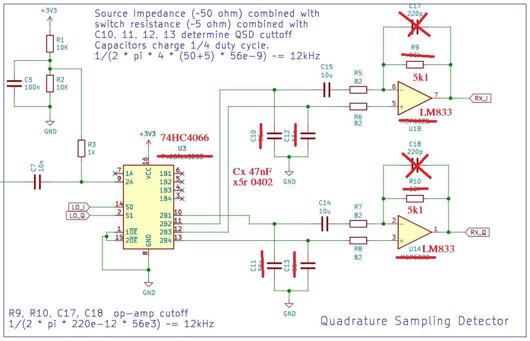
I don’t have all the exact components used in the project.

I made the following substitutions with similar components I had on hand
image

The frontend low rdson analog multiplexer was replaced with a 74HC066 quad analog switch (plus a one hot decoder).

I also lowered the gain of the op-amp difference amplifiers.

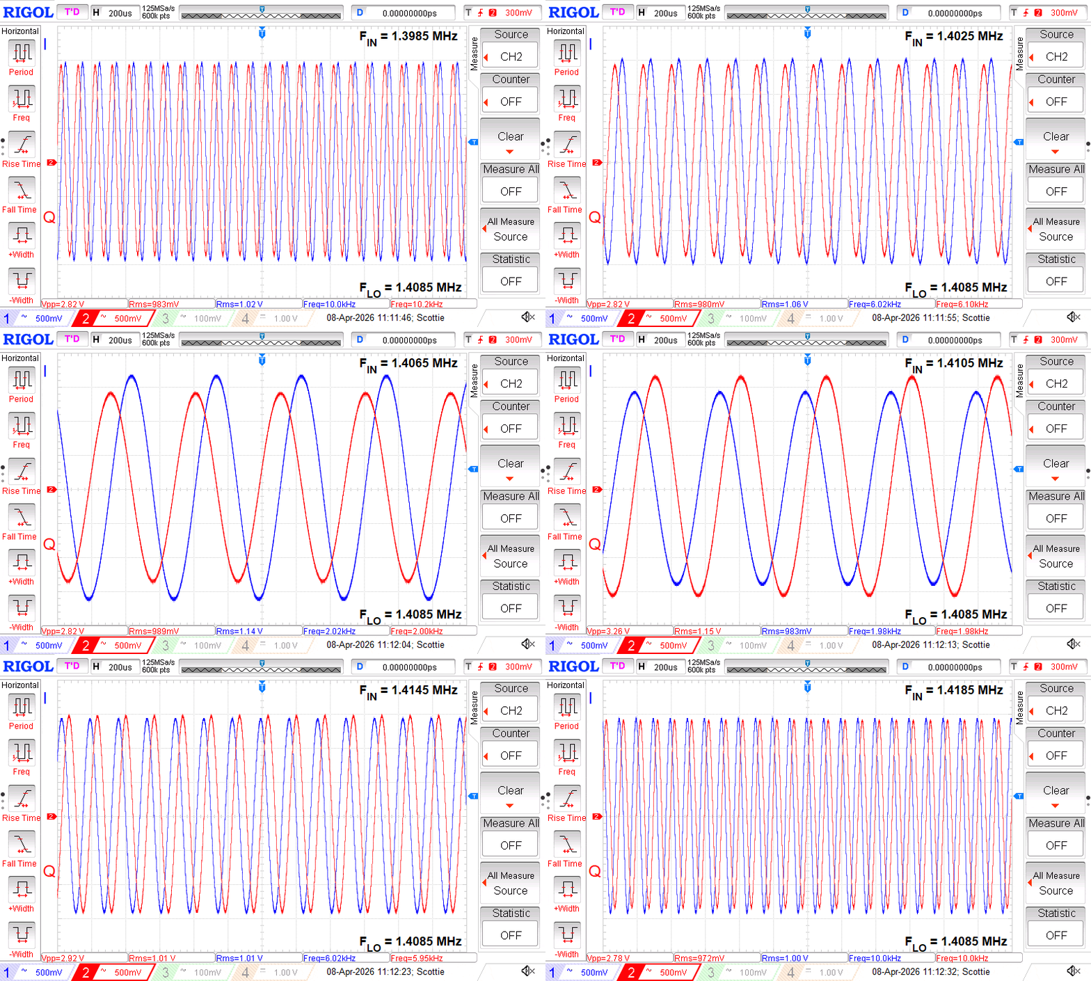
On power up, the picorx software defaults to an LO frequency of 1.4085 MHz.

I used my signal generator to apply a 150 mVpp carrier with a frequency that sweeps from 10 kHz below the pico’s LO to 10 kHz above the pico’s LO.

I get wonderful sinewaves on the output I/Q channels:
image

The quadrature detector has significantly more bandwidth than I expected.

You will notice that for frequencies above the local oscillator the Q signal leads the I signal (and vice versa for frequencies below the LO).

The QSD’s response within 1 kHz of the LO is being partially rejected by the AC-coupled difference amplifiers.

The amplitude response of the I/Q channels is not very well matched (I will have to think about that for a bit)

More to experiment with, but impressive results for the simplicity of the project.

  • Sign in to reply
  • Cancel
  • DAB
    DAB 1 month ago

    Very nice build.

    • Cancel
    • Vote Up +1 Vote Down
    • Sign in to reply
    • Cancel
  • scottiebabe
    scottiebabe 1 month ago

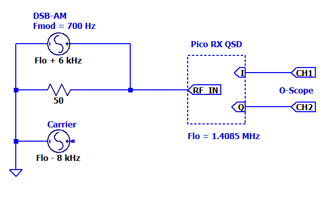
    Here is a spot test of the image rejection performance at 1.4 MHz

    First I apply an AM RF signal 6 kHz above the LO

    image

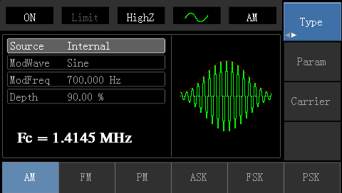
    Signal Generator:

    image

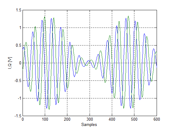
    The recorded I,Q samples from the o-scope

    image

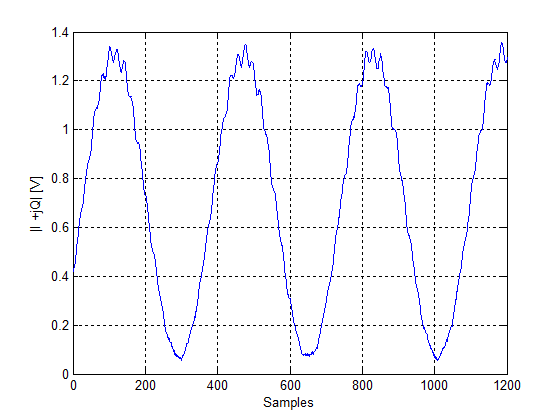
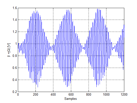
    The magnitude of the complex signal I + jQ

    image

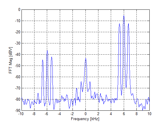
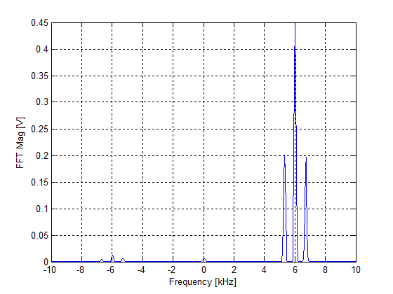
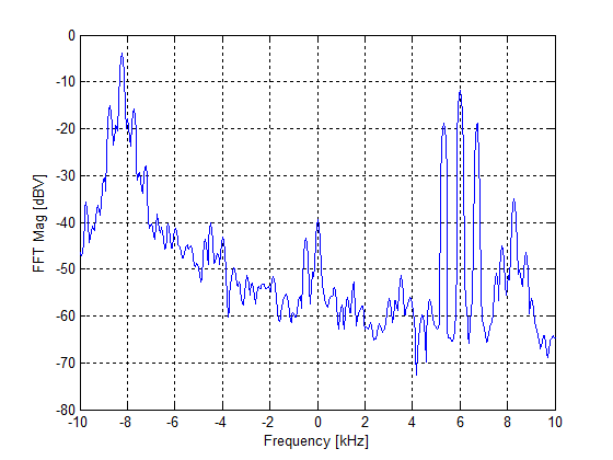
    The FFT of the I,Q samples

    image
    There is a DC offset in the I,Q samples so some power will be seen at 0 Hz. An image of the + 6 kHz signal exists but is attenuated by approximately 30 dB. On a linear scale the image is less noticeable
    image

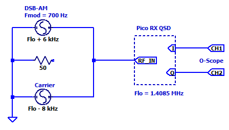
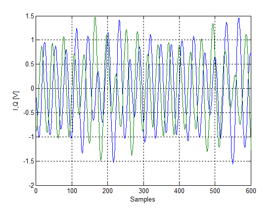
    Adding a unmodulated carrier 8 kHz below the QSD’s LO

    image

    The measured I,Q samples

    image
    image

    In the frequency domain the -8kHz tone (noisy, relaxation oscillator, not crystal controlled) has an image at +8 kHz, but attenuated by 30 dB

    image
    • Cancel
    • Vote Up +5 Vote Down
    • Sign in to reply
    • Cancel
  • shabaz
    shabaz 1 month ago in reply to scottiebabe

    Nice results! There may be noticeable difference with the various substitutions, because of the higher switch resistance (and I don't know how matched they are, although they should be near-identical since they are all on the same chip), plus the load on the sampling capacitors is different for the different inputs of the op-amp (but then again, it was different for the original circuit too). I guess it would be nicer to also have a quad op-amp serving as a same-load buffer for each sampling capacitor, but maybe the effect is negligible (I've not seen any circuits have any buffers either admittedly).

    Regarding the switches, In the past I tried a SD5400CY, perhaps the 3253 is better (it's seen a lot in online circuits, whereas the SD5400 is rarely seen) simply because I thought there was less inside to be mismatched or cause any other switching noise from all the additional MOSFETs in the silicon in the 3253), but I've never compared. SD5400CY is harder to find and too pricey now (in the past it was very cheap) so those are negatives too.

    • Cancel
    • Vote Up +1 Vote Down
    • Sign in to reply
    • Cancel
  • scottiebabe
    scottiebabe 28 days ago

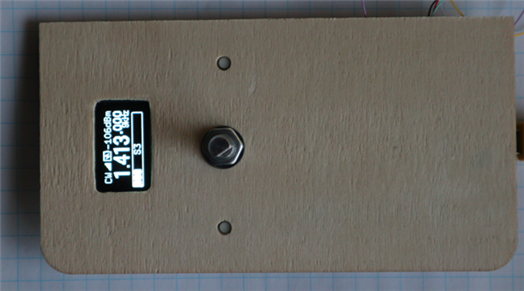
    Spent some time putting the UI bits on a front panel. Most of the configuration options are only available via the physical UI, not the usb serial interface.

    image

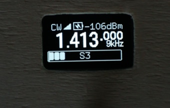
    The author did a nice job on the UI, it looks sharp.

    image

    • Cancel
    • Vote Up +3 Vote Down
    • Sign in to reply
    • Cancel
element14 Community

element14 is the first online community specifically for engineers. Connect with your peers and get expert answers to your questions.

  • Members
  • Learn
  • Technologies
  • Challenges & Projects
  • Products
  • Store
  • About Us
  • Feedback & Support
  • FAQs
  • Terms of Use
  • Privacy Policy
  • Legal and Copyright Notices
  • Sitemap
  • Cookies

An Avnet Company © 2026 Premier Farnell Limited. All Rights Reserved.

Premier Farnell Ltd, registered in England and Wales (no 00876412), registered office: Farnell House, Forge Lane, Leeds LS12 2NE.

ICP 备案号 10220084.

Follow element14

  • X
  • Facebook
  • linkedin
  • YouTube