I've been working on a driver rework, mainly to get rid of the requirement to carry around a bunch of patches to upstream driver code, and also to fix some outstanding issues and introduce some new features.
Most issues have been ironed out so here's the first public release.
Edit: the driver has been included in official RPi kernels. Just run sudo rpi-update to install it.
You still have to install the mixer scripts and add the /etc/modprobe.d file. See my website for details
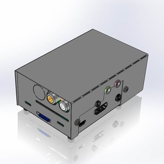
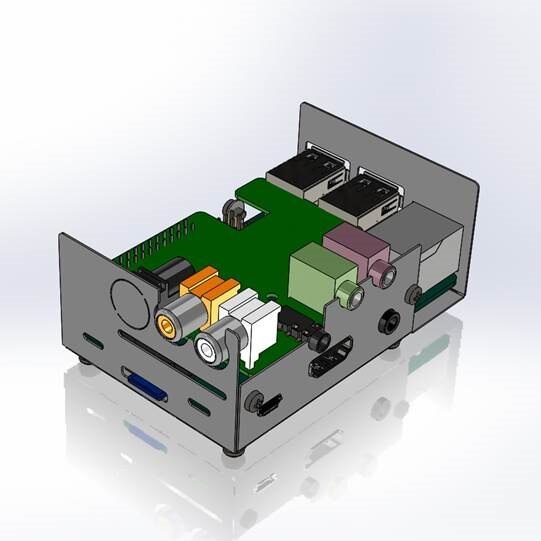
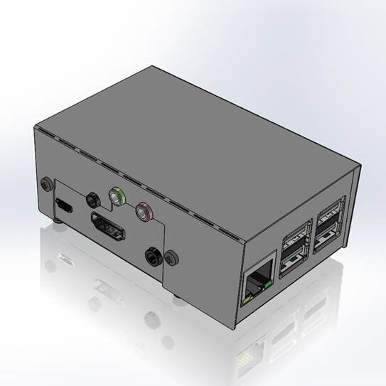
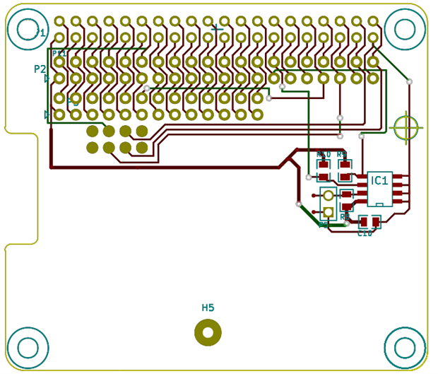
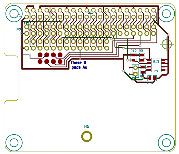
RPi Linux driver for Wolfson / Cirrus Logic Audio Card
Source: https://github.com/HiassofT/rpi-linux/tree/cirrus-ng-4.9.0
Precompiled kernel: http://www.horus.com/~hias/tmp/cirrus/cirrus-ng-linux-4.9.0.tgz
New mixer scripts: http://www.horus.com/~hias/tmp/cirrus/cirrus-ng-scripts.tgz
Important notes:
- The new driver bases on the rather fresh kernel 4.9.0 which means there's some risk of (yet unknown) issues. Use it at your own risk and please run "rpi-update" to get the latest firmware before installing the new driver.
- The soundcard name has been changed from "snd_rpi_wsp" to "RPi-Cirrus", also several ALSA controls have been removed and new ones were added. This means the old usecase scripts and any custom-made scripts will no longer work. Use the new mixer scripts instead of the old usecase/listen scripts.
- The new driver supports setting (and receiving) of the S/PDIF channel status bits (aka AES bits). If you add an ALSA card configuration file this means applications like Kodi can do proper AC3/DTS passthrough. A sample card configuration file (plus the mixer scripts) can be found here: https://github.com/HiassofT/rpi-cirrus-config
- I haven't fully updated the documentation on my website RPi Linux driver for Wolfson / Cirrus Logic Audio Card yet, will do that during the next weeks/months. But except for the things noted above most stuff should still work as in previous driver versions.
Please report back if you tested the driver (either successfully or unsuccessfully), any feedback will help me!
so long,
Hias