element14 Community
element14 Community
    Register Log In
  • Site
  • Search
  • Log In Register
  • About Us
  • Community Hub
    Community Hub
    • What's New on element14
    • Feedback and Support
    • Benefits of Membership
    • Personal Blogs
    • Members Area
    • Achievement Levels
  • Learn
    Learn
    • Ask an Expert
    • eBooks
    • element14 presents
    • Learning Center
    • Tech Spotlight
    • STEM Academy
    • Webinars, Training and Events
    • Learning Groups
  • Technologies
    Technologies
    • 3D Printing
    • FPGA
    • Industrial Automation
    • Internet of Things
    • Power & Energy
    • Sensors
    • Technology Groups
  • Challenges & Projects
    Challenges & Projects
    • Design Challenges
    • element14 presents Projects
    • Project14
    • Arduino Projects
    • Raspberry Pi Projects
    • Project Groups
  • Products
    Products
    • Arduino
    • Avnet Boards Community
    • Dev Tools
    • Manufacturers
    • Multicomp Pro
    • Product Groups
    • Raspberry Pi
    • RoadTests & Reviews
  • Store
    Store
    • Visit Your Store
    • Choose another store...
      • Europe
      •  Austria (German)
      •  Belgium (Dutch, French)
      •  Bulgaria (Bulgarian)
      •  Czech Republic (Czech)
      •  Denmark (Danish)
      •  Estonia (Estonian)
      •  Finland (Finnish)
      •  France (French)
      •  Germany (German)
      •  Hungary (Hungarian)
      •  Ireland
      •  Israel
      •  Italy (Italian)
      •  Latvia (Latvian)
      •  
      •  Lithuania (Lithuanian)
      •  Netherlands (Dutch)
      •  Norway (Norwegian)
      •  Poland (Polish)
      •  Portugal (Portuguese)
      •  Romania (Romanian)
      •  Russia (Russian)
      •  Slovakia (Slovak)
      •  Slovenia (Slovenian)
      •  Spain (Spanish)
      •  Sweden (Swedish)
      •  Switzerland(German, French)
      •  Turkey (Turkish)
      •  United Kingdom
      • Asia Pacific
      •  Australia
      •  China
      •  Hong Kong
      •  India
      •  Korea (Korean)
      •  Malaysia
      •  New Zealand
      •  Philippines
      •  Singapore
      •  Taiwan
      •  Thailand (Thai)
      • Americas
      •  Brazil (Portuguese)
      •  Canada
      •  Mexico (Spanish)
      •  United States
      Can't find the country/region you're looking for? Visit our export site or find a local distributor.
  • Translate
  • Profile
  • Settings
Raspberry Pi
  • Products
  • More
Raspberry Pi
Raspberry Pi Forum Wiring up a PIR to a PiFace Digital2
  • Blog
  • Forum
  • Documents
  • Quiz
  • Events
  • Polls
  • Files
  • Members
  • Mentions
  • Sub-Groups
  • Tags
  • More
  • Cancel
  • New
Join Raspberry Pi to participate - click to join for free!
Featured Articles
Announcing Pi
Technical Specifications
Raspberry Pi FAQs
Win a Pi
Raspberry Pi Wishlist
Actions
  • Share
  • More
  • Cancel
Forum Thread Details
  • Replies 16 replies
  • Subscribers 665 subscribers
  • Views 3099 views
  • Users 0 members are here
  • piface_digital pir
  • rasberry_pi_3_b_plus
Related

Wiring up a PIR to a PiFace Digital2

balanga
balanga over 6 years ago

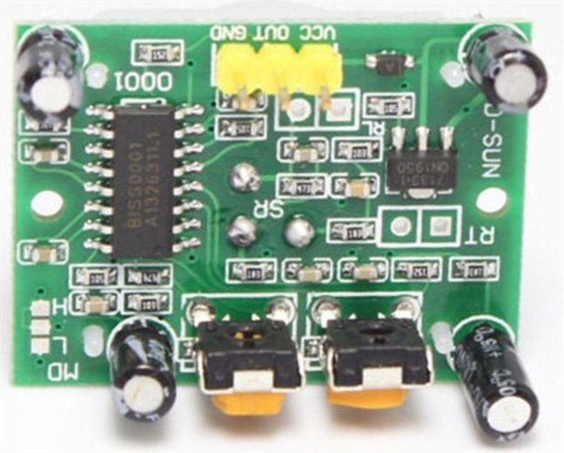
Apologies for this newbie type question, but I can't figure out how to use inputs on a PiFace Digital2.... I would like to connect up a PIR to a to this device and have come across instructions here Review of PiFace Digital , which even has sample code, but it's not clear to me which wires go where.


Any guidance would be appreciated.

  • Sign in to reply
  • Cancel
Parents
  • Gough Lui
    Gough Lui over 6 years ago

    It would help if you could specify the type of PIR you are trying to use? Is it an alarm system type PIR that needs a 12V supply and has a set of NO/NC relay contacts? Or is it a 5V module of sorts that has a logic signal output?


    In general, you need to power the PIR (+ve and GND) and get a signal from the PIR. If the PIR outputs a logic level signal, you could use the digital inputs and connect the PIR output to one of them. If the PIR is a relay output, then you will need to configure a pull-up using resistors to provide an appropriate logic signal.


    - Gough

    • Cancel
    • Vote Up +2 Vote Down
    • Sign in to reply
    • Cancel
  • balanga
    balanga over 6 years ago in reply to Gough Lui

    It's one of these:-

    https://projects.raspberrypi.org/en/projects/physical-computing/13


    On mine the pins aren't labelled, but I assume they are standard as in https://howtomechatronics.com/wp-content/uploads/2015/09/PIR-Sensor-Pinout.jpg?x57244

    • Cancel
    • Vote Up +2 Vote Down
    • Sign in to reply
    • Cancel
  • dougw
    dougw over 6 years ago in reply to balanga

    I think you are correct about the pinout:

    image

    https://www.mpja.com/download/31227sc.pdf

    • Cancel
    • Vote Up +2 Vote Down
    • Sign in to reply
    • Cancel
  • balanga
    balanga over 6 years ago in reply to dougw

    From my searches, I should connect:-


    VCC to GPIO pin 2

    OUT to GPIO pin 7

    GND to GPIO pin 6


    according to https://www.researchgate.net/profile/Zakaria_Rada2/publication/312218161/figure/fig3/AS:449572641218564@1484197878779/GP…


    but am unsure how to map these pins to the PiFace Digital2...


    Having said that this diagram https://projects-static.raspberrypi.org/projects/physical-computing/0cb2cbd34292a05a668aeea3f291ceb3c7d9cd83/en/images/p…  appears to have the pins inverted....


    This diagram http://www.piface.org.uk/static/img/piface_digital_2/pifacedigital2_diagram.png  show two possible locations for VCC and three possible locations for GND. Does it make any difference which I choose? And am I correct in thinking OUT must be one of the eight green terminals?

    • Cancel
    • Vote Up +2 Vote Down
    • Sign in to reply
    • Cancel
  • Gough Lui
    Gough Lui over 6 years ago in reply to balanga

    Operating with and without the PiFace Digital is slightly different. The diagrams you have before are designed for direct GPIO interfacing rather than going through an I/O expander such as the PiFace Digital. The principles are, however, much the same.


    The VCC line should be connected to any of the 5V outputs from the PiFace Digital, the GND line should be connected to any of the GND lines on the PiFace Digital and the OUT line can be connected to any one of the input lines on the PiFace Digital. Your code should read the corresponding input line to find out the status of the PIR.


    - Gough

    • Cancel
    • Vote Up +2 Vote Down
    • Sign in to reply
    • Cancel
  • balanga
    balanga over 6 years ago in reply to Gough Lui

    I finally managed to get this working connecting the OUT pin to the terminal 0 of the input row.  I'm using the following code:-


    # Alarm program by Francesco Balsamo

    #

    # Using a PIR sensor with inverted logic

    #


    from time import sleep


    import pifacedigitalio as pfio

    # import piface.pfio as pfio


    pfio.init()


    while(True):

        for pin_number in range(0,4):

            if pfio.digital_read(pin_number) == 0:

                pfio.digital_write(pin_number+4,1) # Using only the leds

            else:

                pfio.digital_write(pin_number+4,0) # Disabling only the leds

    This switches on LEDs 7,6,5,4  of which 4 is toggled by the PIR, although I can't figure how the code is supposed to work at all...


    I guess this calls for some experimentation. At least I have managed to get the PIR to control one of the LEDs.

    • Cancel
    • Vote Up +1 Vote Down
    • Sign in to reply
    • Cancel
  • Gough Lui
    Gough Lui over 6 years ago in reply to balanga

    The code is pretty simple:

    - while (True) runs the code block that follows infinitely.

    - for pin_number in range(0,4) basically repeats the code for every pin_number in this set (0, 1, 2, 3)

    - if pifo.digital_read(pin_number) == 0 basically says "is this input at pin_number low (as the PIR output goes low when it senses something)?"

    - pfio.digital_write(pin_number+4,1) basically says "lets make LED at pin_number+4 (e.g. for pin 0, then LED4 will) turn on"

    the other case is for if that isn't the case, it turns off the LED.


    This is a rather simple case of polling the input continuously ...


    - Gough

    • Cancel
    • Vote Up +2 Vote Down
    • Sign in to reply
    • Cancel
  • jomoenginer
    jomoenginer over 6 years ago in reply to Gough Lui

    The example that was referenced looks like a PiFace Digital rather than a Digital 2 but should be similar.  From my understanding, the first 4 (0-3) inputs/outputs are tied to the switches (S0-S3) so the example skips these to set LEDs 4-7 by offsetting the value from the 'for/range' loop with "pin_number+4" .  However, the "if" statement is only checking for inputs 0-3 which would be one of the switches or an input from 0-3 but then sets an LED, 4 plus pin_number (4-7), which seems odd.  The example also is using 4 PIR sensors, so if you have only 1 PIR sensor then you could remove the for range loop from the code example.


    If you want an output on say output 4, then you should put the Out from the PIR sensor to Input 4 on the Digital 2.   However, I found the inputs on the Digital 2 are tied to 5v which causes an issue with the Parallax PIR sensor so I place a 10K Ohn resistor between the input port I am using on the Digital 2 to ground (GND) to ensure the PIR reading is clean.  You can disable the pull-up on the input of the Digital 2 but that causes them to float so you would still have to to either tie it high or low depending on the device connected to the Digital 2.


    Reference to PiFace Digital inputs:

    https://pifacedigitalio.readthedocs.io/pifacedigital.html#inputs

    • Cancel
    • Vote Up +3 Vote Down
    • Sign in to reply
    • Cancel
  • balanga
    balanga over 6 years ago in reply to jomoenginer

    After some experimentation I came up with:-


    import time

    import pifacedigitalio as pfio

    start_time = time.time()

    print('start',time.time())


    pfio.init()


    while(True):

        for pin_number in range(0,1):

            if pfio.digital_read(pin_number) == 0:

                print('hello')

                print('elapsed time',time.time() - start_time)


    This produces something like:

    start 1542805023.9155102

    hello

    elapsed time 2.0424649715423584

    hello

    elapsed time 2.0430703163146973

    .

    .

    .

    .

    hello

    elapsed time 4.6204235553741455

    hello

    elapsed time 4.62097692489624

    hello

    elapsed time 4.621711015701294

    hello

    elapsed time 11.211778163909912

    hello

    elapsed time 11.2123863697052

    hello

    elapsed time 11.21294355392456

    hello

    elapsed time 11.213491439819336

    hello

    elapsed time 11.214038372039795

    .

    .

    hello

    elapsed time 13.741790294647217

    hello

    elapsed time 13.742336750030518

    I'm trying to figure out what is going on... I have the Delay Time setting to max, which I think is around 7 secs, so I guess each output of 'hello' is a result of polling which must be taking place every .001 secs over 7 secs.


    How would I go about printing a single 'hello' after motion has been detected?

    • Cancel
    • Vote Up +2 Vote Down
    • Sign in to reply
    • Cancel
  • dougw
    dougw over 6 years ago in reply to balanga

    If sensor == 0 set a flag = 0.

    print if the flag == 1 and the sensor == 0. 

    When the signal == 1 set the flag = 1.

    • Cancel
    • Vote Up +2 Vote Down
    • Sign in to reply
    • Cancel
  • jomoenginer
    jomoenginer over 6 years ago in reply to balanga

    Yeah, what Doug said.


    From my experience, a PIR sensor stays active for a period of time after it senses motion, so I would suspect this is what your are seeing.


    You could put another while loop after the if statement to have it wait for the input pin change state again such as:

    NOTE: This will cause the code to pause while waiting for the pin_state to change to 1 again.

    pin_number = 0
    pin_state = 1
    
    
    while(True):
    
    
        pin_state = pfio.digital_read(pin_number)
        if pin_state == 0:
    
    
            print('hello')
    
    
            print('elapsed time',time.time() - start_time)
    
    
            while pin_state is 0:
                pin_state = pfio.digital_read(pin_number)
                time.sleep(1)


    NOTE: the 'for range' in your code is only looping on 0 so it is a bit unnecessary.

    for pin_number in range(0,1):


    There are a ton of ways to accomplish this in python so you may have to experiment to find what works best for you.


    Did you tie the input pin low with a 10K resistor to ground?  This will ensure the pin is 0 when the signal is not present.

    • Cancel
    • Vote Up +4 Vote Down
    • Sign in to reply
    • Cancel
Reply
  • jomoenginer
    jomoenginer over 6 years ago in reply to balanga

    Yeah, what Doug said.


    From my experience, a PIR sensor stays active for a period of time after it senses motion, so I would suspect this is what your are seeing.


    You could put another while loop after the if statement to have it wait for the input pin change state again such as:

    NOTE: This will cause the code to pause while waiting for the pin_state to change to 1 again.

    pin_number = 0
    pin_state = 1
    
    
    while(True):
    
    
        pin_state = pfio.digital_read(pin_number)
        if pin_state == 0:
    
    
            print('hello')
    
    
            print('elapsed time',time.time() - start_time)
    
    
            while pin_state is 0:
                pin_state = pfio.digital_read(pin_number)
                time.sleep(1)


    NOTE: the 'for range' in your code is only looping on 0 so it is a bit unnecessary.

    for pin_number in range(0,1):


    There are a ton of ways to accomplish this in python so you may have to experiment to find what works best for you.


    Did you tie the input pin low with a 10K resistor to ground?  This will ensure the pin is 0 when the signal is not present.

    • Cancel
    • Vote Up +4 Vote Down
    • Sign in to reply
    • Cancel
Children
  • balanga
    balanga over 6 years ago in reply to jomoenginer

    Many thanks for the help. My python programming skills are non existent so would not have managed to come up with this, although I'm wondering if you have a typo in line 18... Also my electronics knowledge is non existent so using resistors is a no no at this time. However I am now able to use my PIR connected to my PiFace Digital2 to trigger various actions. The next step is to get the PIR to do something with the relays.

    • Cancel
    • Vote Up 0 Vote Down
    • Sign in to reply
    • Cancel
  • jomoenginer
    jomoenginer over 6 years ago in reply to balanga

    Have a look at the post i made yesterday.  The code there does work in my config.


    For the relays, they should be tied to output pins 0 and 1 and would be controlled as such:

    pifacedigital.output_pins[0].turn_on()


    The Relay section of the following doc for the PiFace Digial as the commands to control the relays.

    https://media.readthedocs.org/pdf/pifacedigitalio/latest/pifacedigitalio.pdf


    Note: Udemy has a number of courses discounted to $9.99 for Black Friday in the US.  That might be a good place to find a Python course that will assist your learning. 

    • Cancel
    • Vote Up 0 Vote Down
    • Sign in to reply
    • Cancel
element14 Community

element14 is the first online community specifically for engineers. Connect with your peers and get expert answers to your questions.

  • Members
  • Learn
  • Technologies
  • Challenges & Projects
  • Products
  • Store
  • About Us
  • Feedback & Support
  • FAQs
  • Terms of Use
  • Privacy Policy
  • Legal and Copyright Notices
  • Sitemap
  • Cookies

An Avnet Company © 2025 Premier Farnell Limited. All Rights Reserved.

Premier Farnell Ltd, registered in England and Wales (no 00876412), registered office: Farnell House, Forge Lane, Leeds LS12 2NE.

ICP 备案号 10220084.

Follow element14

  • X
  • Facebook
  • linkedin
  • YouTube