element14 Community
element14 Community
    Register Log In
  • Site
  • Search
  • Log In Register
  • Community Hub
    Community Hub
    • What's New on element14
    • Feedback and Support
    • Benefits of Membership
    • Personal Blogs
    • Members Area
    • Achievement Levels
  • Learn
    Learn
    • Ask an Expert
    • eBooks
    • element14 presents
    • Learning Center
    • Tech Spotlight
    • STEM Academy
    • Webinars, Training and Events
    • Learning Groups
  • Technologies
    Technologies
    • 3D Printing
    • FPGA
    • Industrial Automation
    • Internet of Things
    • Power & Energy
    • Sensors
    • Technology Groups
  • Challenges & Projects
    Challenges & Projects
    • Design Challenges
    • element14 presents Projects
    • Project14
    • Arduino Projects
    • Raspberry Pi Projects
    • Project Groups
  • Products
    Products
    • Arduino
    • Avnet & Tria Boards Community
    • Dev Tools
    • Manufacturers
    • Multicomp Pro
    • Product Groups
    • Raspberry Pi
    • RoadTests & Reviews
  • About Us
    About the element14 Community
  • Store
    Store
    • Visit Your Store
    • Choose another store...
      • Europe
      •  Austria (German)
      •  Belgium (Dutch, French)
      •  Bulgaria (Bulgarian)
      •  Czech Republic (Czech)
      •  Denmark (Danish)
      •  Estonia (Estonian)
      •  Finland (Finnish)
      •  France (French)
      •  Germany (German)
      •  Hungary (Hungarian)
      •  Ireland
      •  Israel
      •  Italy (Italian)
      •  Latvia (Latvian)
      •  
      •  Lithuania (Lithuanian)
      •  Netherlands (Dutch)
      •  Norway (Norwegian)
      •  Poland (Polish)
      •  Portugal (Portuguese)
      •  Romania (Romanian)
      •  Russia (Russian)
      •  Slovakia (Slovak)
      •  Slovenia (Slovenian)
      •  Spain (Spanish)
      •  Sweden (Swedish)
      •  Switzerland(German, French)
      •  Turkey (Turkish)
      •  United Kingdom
      • Asia Pacific
      •  Australia
      •  China
      •  Hong Kong
      •  India
      •  Japan
      •  Korea (Korean)
      •  Malaysia
      •  New Zealand
      •  Philippines
      •  Singapore
      •  Taiwan
      •  Thailand (Thai)
      •  Vietnam
      • Americas
      •  Brazil (Portuguese)
      •  Canada
      •  Mexico (Spanish)
      •  United States
      Can't find the country/region you're looking for? Visit our export site or find a local distributor.
  • Translate
  • Profile
  • Settings
Raspberry Pi Projects
  • Products
  • Raspberry Pi
  • Raspberry Pi Projects
  • More
  • Cancel
Raspberry Pi Projects
Blog HAL-CAM 9001 - Building a Power over Ethernet (PoE) Supply
  • Blog
  • Documents
  • Events
  • Polls
  • Members
  • Mentions
  • Sub-Groups
  • Tags
  • More
  • Cancel
  • New
Join Raspberry Pi Projects to participate - click to join for free!
  • Share
  • More
  • Cancel
Group Actions
  • Group RSS
  • More
  • Cancel
Engagement
  • Author Author: shabaz
  • Date Created: 23 Sep 2016 4:58 AM Date Created
  • Views 11539 views
  • Likes 18 likes
  • Comments 23 comments
  • maxrefdes98
  • power over ethernet
  • o halcam
  • camera_v2
  • ccd
  • rpiintermediate
  • beagleboneblackindustrial
  • beaglebone_black
  • raspberry pi video camera
  • projects
  • cctv
  • raspberry_pi
  • eejournal
  • raspberry pi
  • bbb
  • poe
  • camera
  • video camera
  • maxim
  • raspberry_pi_camera
  • closed circuit television
  • raspberry_pi_projects
  • halcam
  • closed circu*
  • rpi_projects
Related
Recommended

HAL-CAM 9001 - Building a Power over Ethernet (PoE) Supply

shabaz
shabaz
23 Sep 2016

Introduction

This blog post is about powering a new security camera (HAL-CAM 9001) using network cables. These could be cables already installed in an office or home environment, saving costs, or they could be new cables installed indoors or outdoors (using weather resistant cable).


This sub-project is part of the HAL-CAM 9001 project but it is generic enough to suit other scenarios too. It could be used to power a Raspberry Pi remotely for other tasks. Other single board computers (SBCs) can benefit from this project too.


HAL-CAM 9001 doesn’t have a lot of free space inside so this project was made to be ultra-compact; 2cm high and 6x5cm footprint. This project supplies 5V at up to 2.5A.

The schematic and PCB files are attached, ready to be sent to a board manufacturer.

image


What is PoE?

Power over Ethernet is one of these technologies that when you use it, you find you really need it. Over the years it has saved costs, copper, and provided a reliable and safe solution to providing energy to many diverse devices over Ethernet based local area network (LAN) connections.


At its debut, it was said that standards-compliant PoE was effectively one of the few worldwide standards for power so one could take a device and be assured it would work anywhere in the world, in contrast with the mains supply voltages and plug shapes which vary from country to country. And it doesn’t require an electrician to install!


Part of the safety of PoE comes from the ability to automatically and electronically control the delivery of power. By default, the network connection has no substantial power capability enabled and is finger-safe. When the connected device requests power the far end will switch on the supply. Note: the equipment that can supply power is known as the Power Sourcing Equipment (PSE), and the device to be powered is the Powered Device (PD).


With the earlier standard (IEEE 802.3af) the request was as simple as having a 25k resistor across a couple of pins. If the resistor was present, then the far end would turn on the power. This solution provided about 13W of power to the PD. The later standard IEEE 802.3at nearly doubled this capability, to just over 25W of power. This later standard had a more complicated method of enabling power; the PD would provide a varying load over time in a special combination that would allow the PSE to detect that the PD was an 802.3at capable device and then supply up to one of four particular levels of power. Once this was achieved it was possible to signal information in Ethernet packets to further refine the power requirements.


Today Universal PoE (UPOE) has more than doubled the power capability to 60W – equivalent to an incandescent light bulb!

image


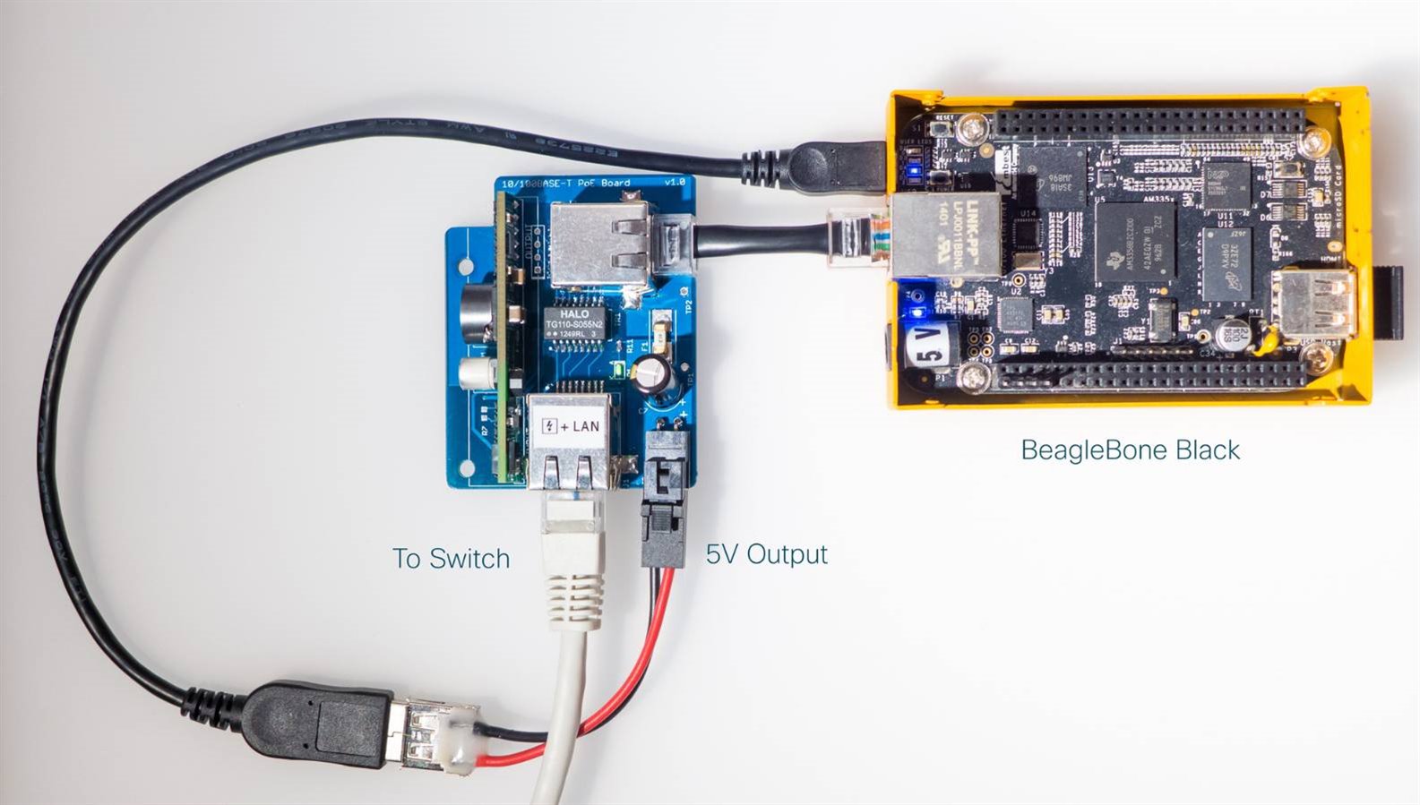
This project provides IEEE 802.3af and 802.3at standards based power capability. The output is at 5V, capable of up to 2.5A (i.e. up to 12.5W). This level of output is ideal for remotely powering HAL-CAM 9001, or other Raspberry Pi projects, BeagleBone Black (BBB) or other single board computers (SBCs).
image


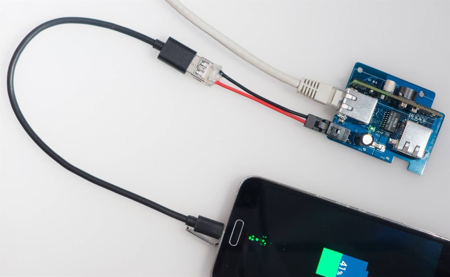
Note that the powered device doesn’t actually need to have an Ethernet connection at all. It is possible to use PoE to charge your mobile phone.
image


How do I get PoE?

Assuming standards-based PoE is required then the best way is to pick up a switch with 802.3af or 802.3at capability. In the UK for consumer use the 802.3af compliant 8-port TP-LINK TL-SG1008P costs about £50 from Amazon and provides 4 devices with up to 13W of power each, simultaneously (I have not tried this switch so it isn’t a recommendation, just a pointer to what is out there).


There are also so-called ‘PoE Injector’ adapters, also misleadingly called 2-port PoE switches sometimes. These are not great because often they are not IEEE 802.3af or 802.3at compliant and may supply power all the time; they are therefore not very green because their power cannot be shut down electronically. A true standards compliant PoE capable switch is the far better choice and doesn’t cost much as mentioned earlier, considering it can power up to four devices.


At the device end, it needs to support the same standard. If the device doesn’t support PoE then an off-the-shelf external PoE adapter can be used; it is standards compliant and taps off the supply to be used to power the device.


Building It
image

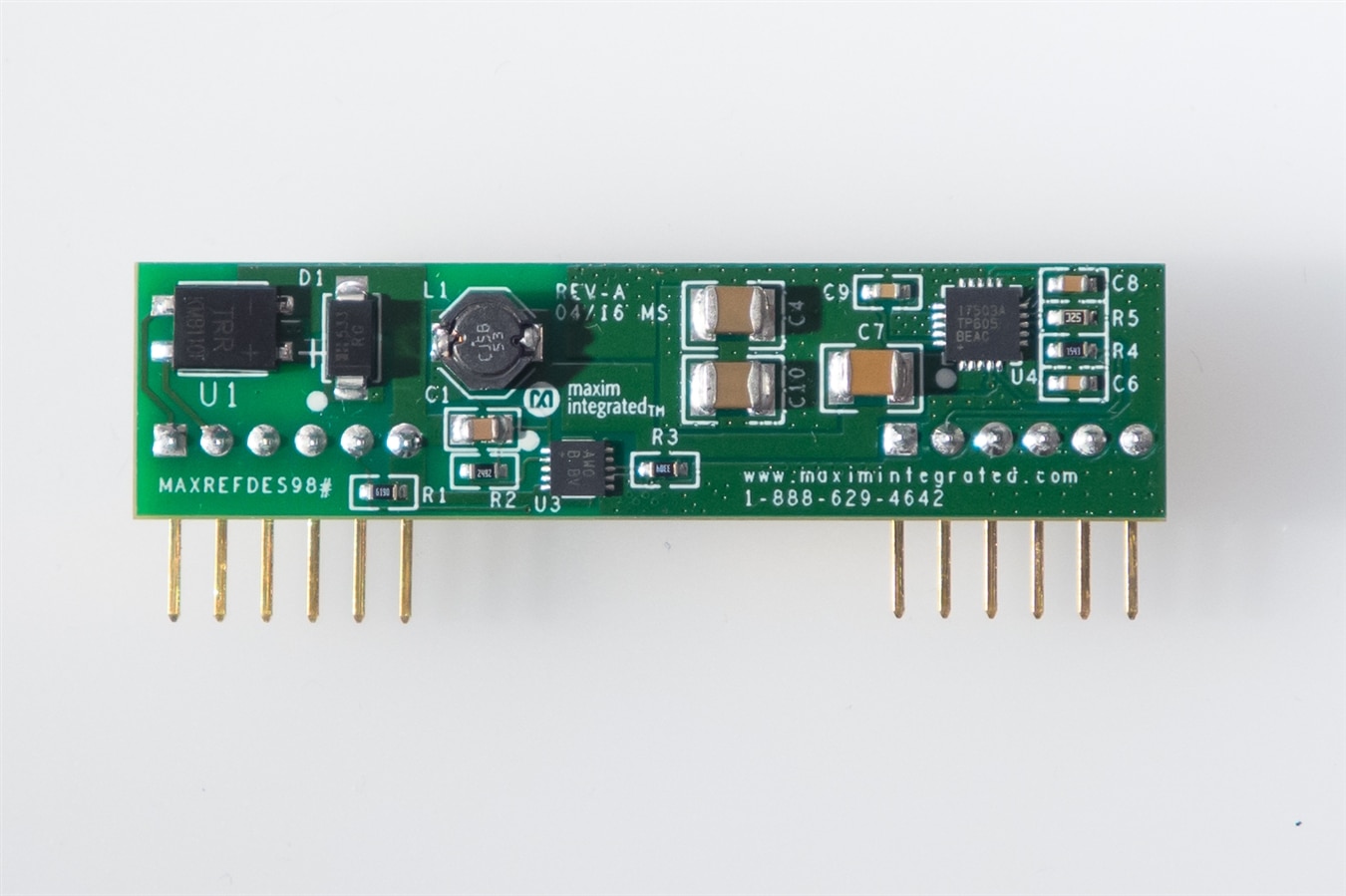
The schematic is shown below; it is really simple because most of the functionality is contained in Maxim’s MAXREFDES98MAXREFDES98 board which contains a DC-DC converter and the circuitry to handle the standards negotiation. The rest of the board mainly consists of the Ethernet transformers and connectors. Note that it would be wise to add some suppression circuitry as detailed in the original HAL-CAM blog page; I forgot to add it to this revision 1 PCB but the same method (TVS diodes) can be used as in the original blog post. At some stage I will update this blog post with revision 2 files which will correct this omission.

image


To construct this project, solder up the smallest parts first (the resistors and capacitors), ending with the largest parts. The fuse is optionally available in a socket which will fit the board but I chose to save some cost and directly solder the fuse.


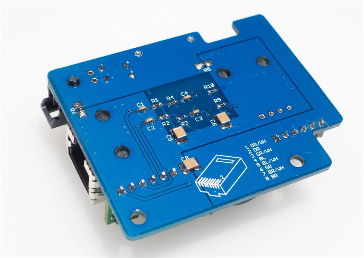
Network cables are available in short lengths but I wanted an extremely short length (a few cm) for fitting inside HAL-CAM 9001 so I used an RJ45 tool to do that. The back of the PCB has a reference indicating which color wire goes where.
image


Testing It

There is not much chance of error during assembly since there are so few parts in this project (the part values are in the schematic but a list of components will be published in the next few days). I connected this project via the longest length of network cable that I had (5m long) to a switch, enabled PoE on it (some switches require configuration for this) and then used a multimeter to confirm 5V was present on the output supply connector. The on-board LED was lit too, confirming that the board was receiving power. The multimeter confirmed the correct output so I proceeded to plug it into the Pi and verified that the Ethernet link came up and I had network connectivity. I can now issue a shutdown command to the Pi remotely using SSH, and then configure the switch to disable power. Whenever I want to turn the Pi on, I can configure the switch to turn on the PoE capability.


There are additional tests that should be done (such as confirm the voltage output under changing loads, verify the ‘eye diagram’ for the signals over the network cable, check for RF interference and checking throughput to see if there are any packet errors occurring). These will be done later at some stage; for now the board is functioning well enough to continue HAL-CAM 9001 development.


Summary

PoE is easy to use and it can be useful to be able to retro-fit non-PoE devices with the capability. The Maxim module makes this really easy. The PCB files are attached ready to send to a manufacturer. Note that the PCB also has some additional “features” (see photo below) which can be hack-sawed off and put aside for now (they are for unrelated mini-projects which will be documented at some later stage; feel free to guess what they are! It is not too difficult).

image


See also:


HAL-CAM 9001 – Building a New Security Camera

Attachments:
poe-export-1.zip
  • Sign in to reply

Top Comments

  • mcb1
    mcb1 over 9 years ago +4
    Nice project. It should help with that heat problem nicely ....
  • clem57
    clem57 over 9 years ago +4
    shabaz up until now, I looked at POE as redundant. But now you gave me convincing arguments to re examine. Thanks for the research. Clem
  • jw0752
    jw0752 over 9 years ago +3
    Hi Shabaz, Thanks for posting this interesting and useful build. I will be following your future refinements. John
  • shabaz
    shabaz over 9 years ago in reply to vanthome

    Hi Thomas,


    The board files can be viewed with the free 'gerbv' software, however if you wish to make modifications then the schematic would need to be entered manually into your preferred CAD package, because I use custom scripts to assist to generate these. The gerber files are ready to be sent as-is to almost any board manufacturer.

    • Cancel
    • Vote Up 0 Vote Down
    • Sign in to reply
    • More
    • Cancel
  • vanthome
    vanthome over 9 years ago in reply to shabaz

    Sure, the cost are totally fine! the schematics you shared, in which tool can I open them? I tried in eagle and kicad but could not import them in any of them.

    • Cancel
    • Vote Up 0 Vote Down
    • Sign in to reply
    • More
    • Cancel
  • shabaz
    shabaz over 9 years ago in reply to vanthome

    Hi Thomas,


    Thanks for the feedback!

    I''ll get the BoM incorporated into the post soon, however it is pasted below. The 'Code' column are Farnell order codes (they can be entered into the Newark website too). Unfortunately I've not updated the PCB yet for the cheaper module. Still, for a 1-off board, the extra cost isn't too much to stomach. If you're planning to build more than a couple of them then it would be worthwhile to update the PCB with the cheaper module. Also the current PCB is confirmed working since it has been built (and a colleague has built one too using the same files, although he has to test his yet).

    Also, a couple of notes:

    * The fuse F1 only comes in packs of 10 which makes it expensive, you may wish to use a 0 ohm resistor/wire link if you're very careful!

    * There are some parts with IDs >99, e.g. C100, C101, R100 etc. Those are optional. They are not needed for PoE, but the PCB has a cut-off section which is a 3.3V USB-Serial UART board that is useful for the Pi. If you don't want to build the USB-Serial board then you don't need those parts. Basically, the parts list is for the PoE board and the USB-Serial board. I left the ID >99 parts in the list, because they cost very little, and the USB-Serial is a useful thing. There is a photo of the USB-Serial board assembled below.


    PoE Board and USB-Serial Parts List
    -----------------------------------                                  
    Part           Qty  Code        Value             Device                Description                                                                                                                  
    C1,C2,C3,C4    4    1759102     10n               C-EUC0603             CAPACITOR, European symbol                                                                                                   
    C5,C6,C8,C103  4    1886055     1n                C-EUC1210             CAPACITOR, European symbol                                                                                                   
    C7             1    1219473     220u              CAP-POL-8-3_5         Polarised capacitor 8mm dia 3.5mm pitch                                                                                      
    C104,C105      2    1759122     100n              C-EUC0603             CAPACITOR, European symbol                                                                                                   
    C101,C102      2    9227792     1u                C-EUC0805             CAPACITOR, European symbol                                                                                                   
    D1,D101        2    1685066     LED YELLOW        LED-0603-YELLOW         LED 0603 e.g. Rohm SML-310MTT86                                                                                              
    D102           1    1685063     LED GREEN         LED-0603-GREEN        LED 0603 e.g. Rohm SML-310MTT86                                                                                              
    F1             1    9922180     3A                USER_LITTELFUSE154154 Littelfuse 154 series 1A is 0154001.DR   Farnell 9943633                                                                     
    J1,J2          2    2076095     PWR+DATA          85543-7001            85543-7001 Molex Cat 5e shielded RJ45 socket Farnell 2076095                                                                 
    J3             1    2494362     5V 2.5A OUT       ULTRA-FIT-2-HORIZ     Ultra-Fit 2-way vertical mount                                                                                               
    J3PLUG         1    2494337     Plug 5V 2.5A      ULTRA-FIT-2-PLUG      
    J101           1    9786473     54819-0572        54819-0572            Molex USB Mini 54819-0572 Farnell 9786473                                                                                    
    J102           1    3418388     SIL3              SIL3                                                                                                                                               
    R1,2,3,4,9,10  6    9331549     75R               R-EU_R0603            RESISTOR, European symbol                                                                                                    
    R5,R6          2    2309111     0R                R-EU_R1206            RESISTOR, European symbol                                                                                                    
    R7,R8          1                DNF (Do Not Fit)  R-EU_R0603            RESISTOR, European symbol                                                                                                    
    R11            1    9331018     330R              R-EU_R0603            RESISTOR, European symbol                                                                                                    
    R101           1    2141628     10M               R-EU_R0603            RESISTOR, European symbol                                                                                                    
    R102,R103      2    9330593     150R              R-EU_R0603            RESISTOR, European symbol                                                                                                    
    TR1            1    1644276     B78476A8247A003   B78476A8247A003       B78476A8247A003 EPCOS 10/100Base--T Magnetics                                                                                
    U1             1    2610453     MAXREFDES98       MAXREFDES98           MAXREFDES98 PoE Module 5V output 2.5A                                                                                        
    U101           1    1296592     MCP1700T-3302E/TT MCP1700T              MCP1700T fixed regulator SOT-23 package                                                                                      
    U102           1    2434893     MCP2221-I/SL      MCP2221-2-I/SL        MCP2221 SOIC package                                                                                                       


    USB-Serial

    Pin connections to the Pi are:

    Blue=pin 14

    Green=pin 10

    Yellow=pin 8

    image

    • Cancel
    • Vote Up +2 Vote Down
    • Sign in to reply
    • More
    • Cancel
  • vanthome
    vanthome over 9 years ago

    Hi, shabazgreat article! Can you please publish the PCB design files with the change you mention in the blog? Also the BOM does not seem to be published yet.

    • Cancel
    • Vote Up 0 Vote Down
    • Sign in to reply
    • More
    • Cancel
  • Workshopshed
    Workshopshed over 9 years ago in reply to clem57

    Remote cameras do seem to be a good use-case for POE. Also perhaps a Wifi access points in a large building.

    • Cancel
    • Vote Up +3 Vote Down
    • Sign in to reply
    • More
    • Cancel
<>
element14 Community

element14 is the first online community specifically for engineers. Connect with your peers and get expert answers to your questions.

  • Members
  • Learn
  • Technologies
  • Challenges & Projects
  • Products
  • Store
  • About Us
  • Feedback & Support
  • FAQs
  • Terms of Use
  • Privacy Policy
  • Legal and Copyright Notices
  • Sitemap
  • Cookies

An Avnet Company © 2026 Premier Farnell Limited. All Rights Reserved.

Premier Farnell Ltd, registered in England and Wales (no 00876412), registered office: Farnell House, Forge Lane, Leeds LS12 2NE.

Follow element14

  • X
  • Facebook
  • linkedin
  • YouTube