element14 Community
element14 Community
    Register Log In
  • Site
  • Search
  • Log In Register
  • Community Hub
    Community Hub
    • What's New on element14
    • Feedback and Support
    • Benefits of Membership
    • Personal Blogs
    • Members Area
    • Achievement Levels
  • Learn
    Learn
    • Ask an Expert
    • eBooks
    • element14 presents
    • Learning Center
    • Tech Spotlight
    • STEM Academy
    • Webinars, Training and Events
    • Learning Groups
  • Technologies
    Technologies
    • 3D Printing
    • FPGA
    • Industrial Automation
    • Internet of Things
    • Power & Energy
    • Sensors
    • Technology Groups
  • Challenges & Projects
    Challenges & Projects
    • Design Challenges
    • element14 presents Projects
    • Project14
    • Arduino Projects
    • Raspberry Pi Projects
    • Project Groups
  • Products
    Products
    • Arduino
    • Avnet Boards Community
    • Dev Tools
    • Manufacturers
    • Multicomp Pro
    • Product Groups
    • Raspberry Pi
    • RoadTests & Reviews
  • About Us
  • Store
    Store
    • Visit Your Store
    • Choose another store...
      • Europe
      •  Austria (German)
      •  Belgium (Dutch, French)
      •  Bulgaria (Bulgarian)
      •  Czech Republic (Czech)
      •  Denmark (Danish)
      •  Estonia (Estonian)
      •  Finland (Finnish)
      •  France (French)
      •  Germany (German)
      •  Hungary (Hungarian)
      •  Ireland
      •  Israel
      •  Italy (Italian)
      •  Latvia (Latvian)
      •  
      •  Lithuania (Lithuanian)
      •  Netherlands (Dutch)
      •  Norway (Norwegian)
      •  Poland (Polish)
      •  Portugal (Portuguese)
      •  Romania (Romanian)
      •  Russia (Russian)
      •  Slovakia (Slovak)
      •  Slovenia (Slovenian)
      •  Spain (Spanish)
      •  Sweden (Swedish)
      •  Switzerland(German, French)
      •  Turkey (Turkish)
      •  United Kingdom
      • Asia Pacific
      •  Australia
      •  China
      •  Hong Kong
      •  India
      •  Korea (Korean)
      •  Malaysia
      •  New Zealand
      •  Philippines
      •  Singapore
      •  Taiwan
      •  Thailand (Thai)
      • Americas
      •  Brazil (Portuguese)
      •  Canada
      •  Mexico (Spanish)
      •  United States
      Can't find the country/region you're looking for? Visit our export site or find a local distributor.
  • Translate
  • Profile
  • Settings
Raspberry Pi Projects
  • Products
  • Raspberry Pi
  • Raspberry Pi Projects
  • More
  • Cancel
Raspberry Pi Projects
Blog Measure the Analogue Front-end of Data Acquisition Board for Pi Pico
  • Blog
  • Documents
  • Events
  • Polls
  • Members
  • Mentions
  • Sub-Groups
  • Tags
  • More
  • Cancel
  • New
Join Raspberry Pi Projects to participate - click to join for free!
  • Share
  • More
  • Cancel
Group Actions
  • Group RSS
  • More
  • Cancel
Engagement
  • Author Author: Jan Cumps
  • Date Created: 5 Nov 2023 12:05 PM Date Created
  • Views 1617 views
  • Likes 9 likes
  • Comments 11 comments
  • rpiintermediate
  • ADC (Analog-to-Digital Converter)
  • pico
  • data acquisition
  • ads1115
  • rp2040
  • daq
  • raspberry_pi_projects
  • adc
  • test&measurement
  • pi pico
Related
Recommended

Measure the Analogue Front-end of Data Acquisition Board for Pi Pico

Jan Cumps
Jan Cumps
5 Nov 2023
Measure the Analogue Front-end of Data Acquisition Board for Pi Pico

 shabaz designed a Data Acquisition Board (DAB ) for the Pico:  Data Acquisition Board for Pi Pico . In this post, I'll measure the analogue front-end, and show how it behaves within its +- 4V range.

image

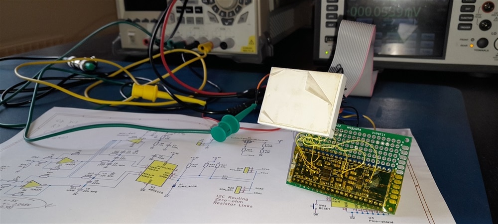
I've attached probes to the main points of interest. Then applied input values between +4 V and -4 V, in steps of 0.5 V.
The data is collected in a spreadsheet to try and spot trends and stability.
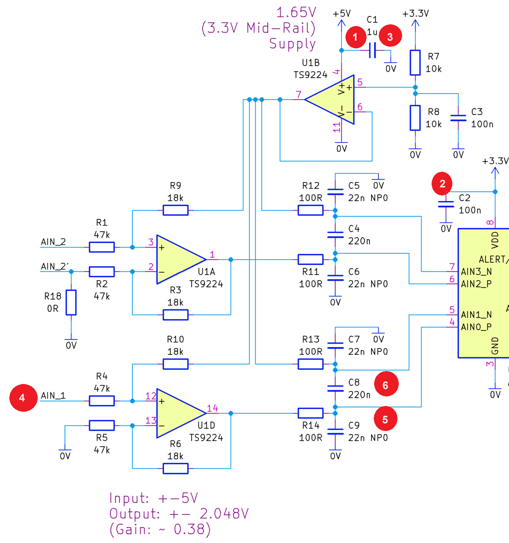
Measurement points

1 5V supply power
2 3.3V supply power
3 GND supply power ground
4 AIN_1 test voltage input
5 AIN1_P opamp U1D out output
6 AIN1_N opamp U1B out virtual ground

image

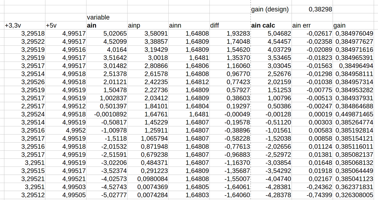
Test results and calculations

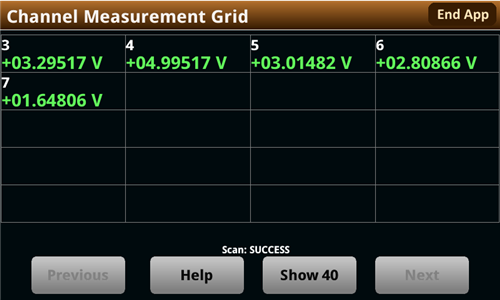
  • The first 5 columns reflect the testing points of the previous chapter (without GND), and are all measured (in V).
  • diff: ainp - ainn, in essence, it is input * gain, measured
  • ain calc: diff * theoretical gain, (circuit gain, based on resistors used, is 0.38298), should ideally match ain
  • ain err: ain -  ain calc. How much does the calculated ain differ from the actual input
  • gain: what is the actual gain of U1D at each sample

image

Graphs and trends

Error

Let's first look at the error across the range:

image

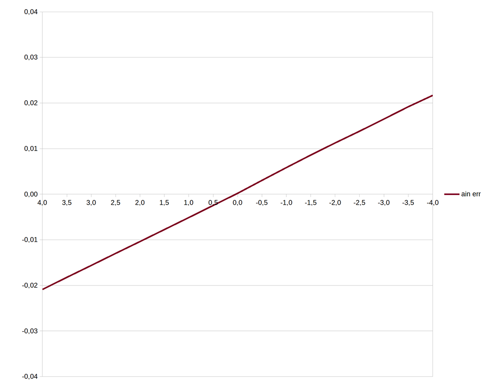
This is very linear. and crosses at 0V input. That points to (discuss if you have a different opinion):

  • no offset error
  • the gain isn't 0,38298, but closer to 0.385

Here is the same graph if I set the gain for calculations to 0.385:

image

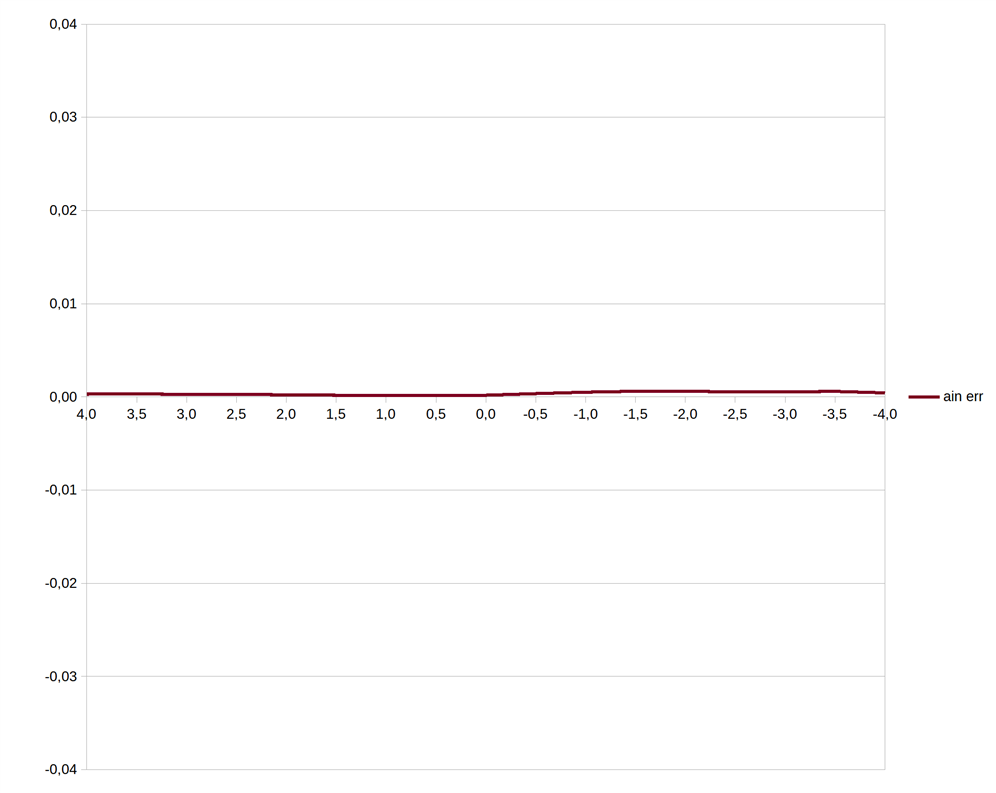
This is good news for calibration algorithms. Easy to program as a function. No lookup tables needed.
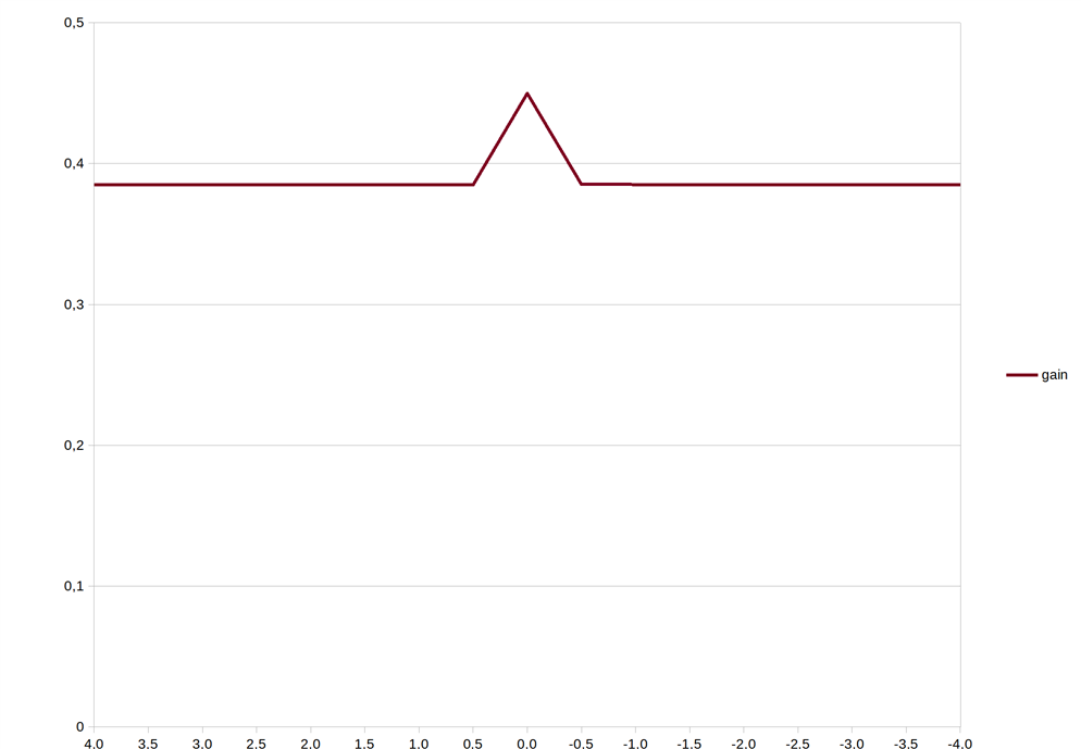
Gain

The gain is also consistent across the range. I blame the peak at 0 to calculation error factor (discuss). Everything is close to 0 at that point.
I did double-check the values though.

image

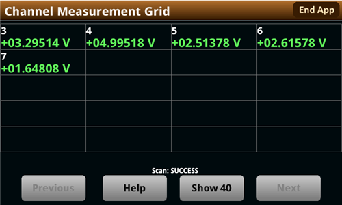
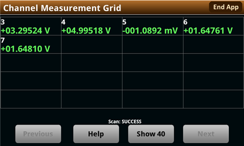
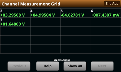
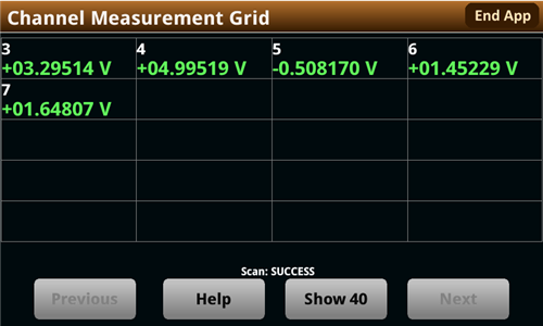
Here are all measurements:

image image

image image

image image

image image

image image

image image

image image

image image

image image

image image

And the spreadsheet:

8311.measure_analogue_frontend.ods.zip

  • Sign in to reply
Parents
  • shabaz
    shabaz over 1 year ago

    Hi Jan,

    These are very comprehensive measurements, it's great to see all the detail at each measurement point! This will make it simpler to code for it, now knowing how best to compensate for it (and easier now to suggest a calibration procedure for users, since they would need to apply a voltage that they can confirm with their multimeter).

    Thanks for the awesome work.

    Also, great testbed! Neat idea to use the breadboard as an interface like that : ) 

    • Cancel
    • Vote Up 0 Vote Down
    • Sign in to reply
    • More
    • Cancel
Comment
  • shabaz
    shabaz over 1 year ago

    Hi Jan,

    These are very comprehensive measurements, it's great to see all the detail at each measurement point! This will make it simpler to code for it, now knowing how best to compensate for it (and easier now to suggest a calibration procedure for users, since they would need to apply a voltage that they can confirm with their multimeter).

    Thanks for the awesome work.

    Also, great testbed! Neat idea to use the breadboard as an interface like that : ) 

    • Cancel
    • Vote Up 0 Vote Down
    • Sign in to reply
    • More
    • Cancel
Children
No Data
element14 Community

element14 is the first online community specifically for engineers. Connect with your peers and get expert answers to your questions.

  • Members
  • Learn
  • Technologies
  • Challenges & Projects
  • Products
  • Store
  • About Us
  • Feedback & Support
  • FAQs
  • Terms of Use
  • Privacy Policy
  • Legal and Copyright Notices
  • Sitemap
  • Cookies

An Avnet Company © 2025 Premier Farnell Limited. All Rights Reserved.

Premier Farnell Ltd, registered in England and Wales (no 00876412), registered office: Farnell House, Forge Lane, Leeds LS12 2NE.

ICP 备案号 10220084.

Follow element14

  • X
  • Facebook
  • linkedin
  • YouTube