Table of Contents
- Introduction
- What’s wrong with Off-the-Shelf?
- Building and Running the Prototype
- Color Temperature: What is it?
- Blending Colors
- Compile-Time vs Run-Time Calculations
- Creating New Projects with PicoChroma
- Calibration
- Using a Color Checker
- XML Format LED PWM Tables
- How was this Project Created?
- Next Steps
- Summary
Introduction
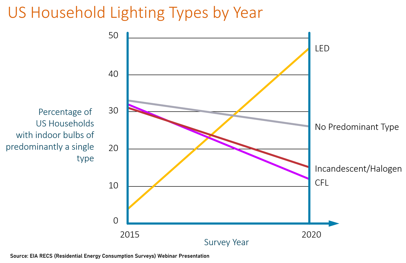
This project was motivated by the desire to get better lighting. It is well-known that often LED lighting can look strange, because it’s not quite similar to existing lighting, whether it be natural lighting or artificial. For instance, sometimes there is a reddish or yellow, or blue tint that might not look right. It would be nice to be able to adjust it. It could have a positive impact on alertness/productivity during the day, or help people relax in the evening. Some hospitals have trialed adjustable LED lighting near patient beds, and claim their results show that patients fall asleep faster at night when the lighting is controlled. Some manufacturers promote systems for deployment in schools, claiming children perform better (perhaps through improved alertness), and they state that they have done studies to demonstrate it. For many people, nice lighting can simply brighten the mood and improve their work or living environment. Some interior designers still recommend incandescent lights, which are energy inefficient and an anachronism now. The transition to LEDs for lighting has been stunning.
When it comes to photography and video, adjustable lighting becomes critical, because it greatly affects how colors are interpreted by the camera and editing tools. If you’ve sometimes seen washed-out camera snapshots, or where people’s faces look odd, either too grey or too orangey, then you’ve experienced color-related problems caused by incorrect settings (known as white balance adjustment) by the camera. The camera firmware often incorrectly assumes that colors in the image might actually be closer to white, and therefore it applies a tint and tries to correct it, effectively altering the skin color, and it is noticeable because people are aware of what people should look like. Applying studio lighting that does not match the rest of the lighting will make it very difficult for the camera to select the correct adjustment, and it cannot be easily corrected in editing either. Photos then end up having oranges or blues where there shouldn’t be such colors.
One very popular method to implement adjustability is to use two (or more) LED colors and blend the light output in varying controlled amounts. You can buy bulbs that are adjustable; they may come with a wireless remote control. Some Philips bulbs are designed for retrofit, using existing dimmer controls (dimming those specific bulbs will shift the light output to be warmer). Internally the bulbs contain two different LED types as mentioned. Others bulbs are part of IoT solutions and they can be automatically controlled, which is great because then they can provide coordinated lighting to suit the time of day or your current mood.
For photography and video work, it is possible to get really nice panel lights with two sets of LEDs across them, often battery-powered. They are really versatile.
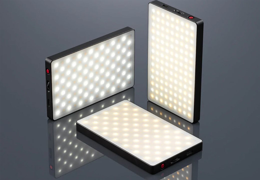 (Image Source: Kenro website)
Another option is to go for full-color (RGB) adjustable lights; useful if special effects are needed, but they can also solve a problem that is described further below.
This project provides an open-source method to implement adjustable lighting for home use, or for studio/photo/video lighting, especially for situations where an off-the-shelf system might not meet all requirements. It could be paired with any IoT solution with a bit of effort. The key benefit of this project is that it sorts out the calculations for the LED adjustments, so all you need to do (or all the IoT solution needs to do) is select the desired color and brightness. This project also covers how to calibrate the system at a low cost, so that the light color is repeatable and replicable. That’s especially important for matching multiple lights in an environment.
My initial small requirement was simply to get better lighting for a camera microscope where a ring light was not performing as well as desired, and the camera image had some glare and a lot of noise. A friend suggested that a strip light closer to the subject would help, and it did! Trouble is, I couldn’t find a suitably compact strip light. After a bit of thinking and feature creep, it was decided to make a more general-purpose system that could be used for all sorts of lighting applications, and it is called PicoChroma. It controls two sets of LEDs to create different lighting environments. PicoChroma could be used to build custom lights.
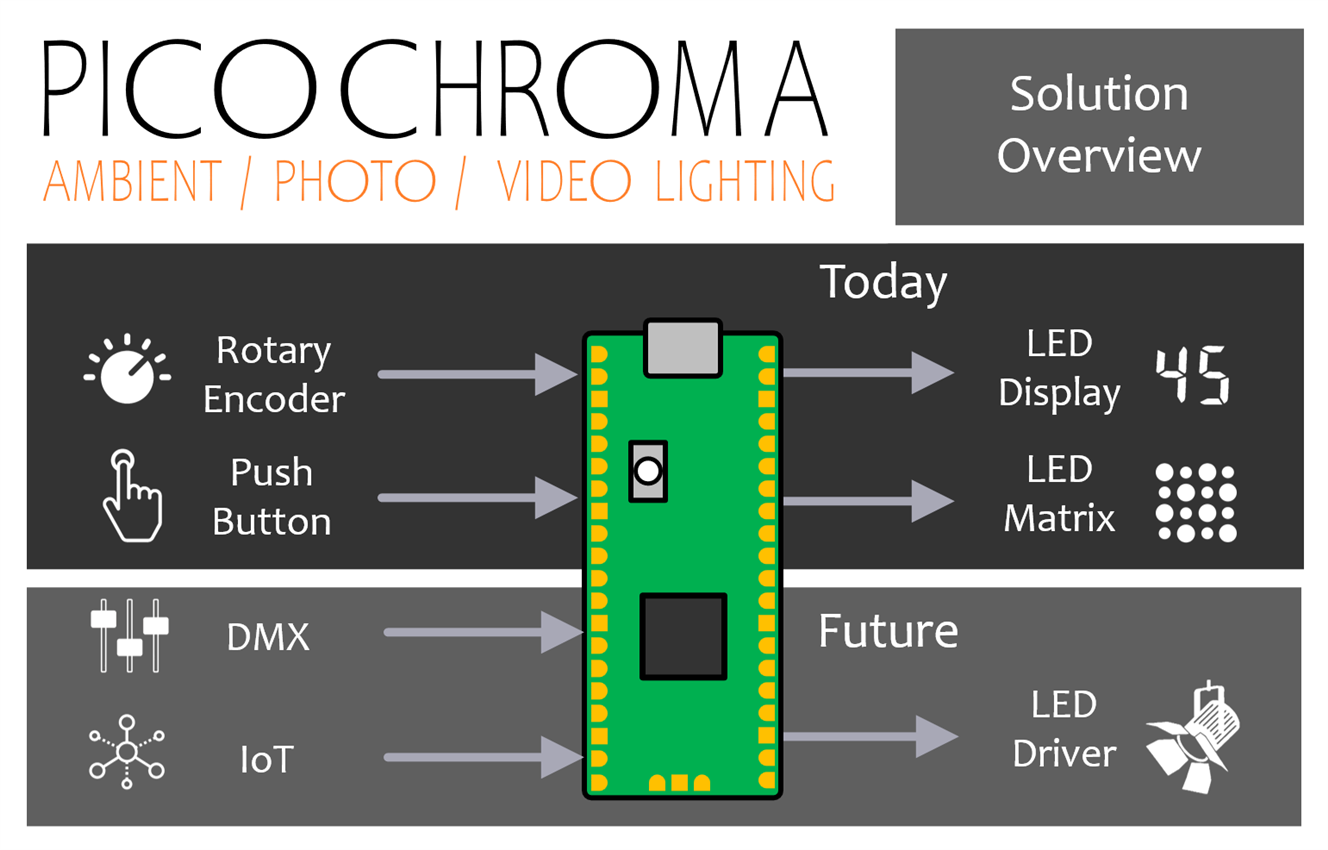
From a hardware perspective, the project is really simple; a single Pi Pico microcontroller board and a couple of low-power LEDs are sufficient to test it out. Then, it is possible to add controls to adjust the light output, and to add more powerful or better-quality sets of LEDs and drivers.

The photo above shows the prototype. There’s not much to it. A single rotary control (rotary encoder) and push-button are used to adjust the color (or more specifically the color temperature, see below for an explanation), and brightness, and there is a 7-segment LED display to show the current settings. A DIY strip of LEDs of alternating colors was connected to it via MOSFETs. Everything is managed by the Pi Pico (sitting on a Pico-Eurocard development board, but that’s not essential). The buttons and rotary control and 7-segment display are not essential either, because everything can be controlled via the optional USB port connection. In the future, I’d like to add DMX local control, and remote operation using either Bluetooth LE (BLE) or Wi-Fi (the Pico-W has in-built Wi-Fi and it would be straightforward to build on this capability).
This blog post explains how the PicoChroma works, how to code and build it, and how to calibrate it.
What’s wrong with Off-the-Shelf?
Nothing is wrong with off-the-shelf options as such. However, one benefit versus a ready-made light is that PicoChroma could be a lot cheaper. I couldn’t find a low-cost ready-made light with a color temperature value display; most of them have a button or rotary controls with no indication. Another benefit is that the desired amount of LEDs can be used, and the desired shape can be created to suit needs. For instance, this project could theoretically be extended massively, to provide an accurate color temperature adjustment for home lighting. That’s something that doesn’t seem to be available commercially currently. Or, it could be modified to provide DMX-controlled adjustable color temperature lighting.
Building and Running the Prototype
Note: For this section, I’ll assume the reader knows what color temperature means. The term is described in later sections.
To get going quickly, this is the minimum viable circuit that is sufficient to experiment with the code; it’s not a practical light at this stage, this is just to quickly try out the code:
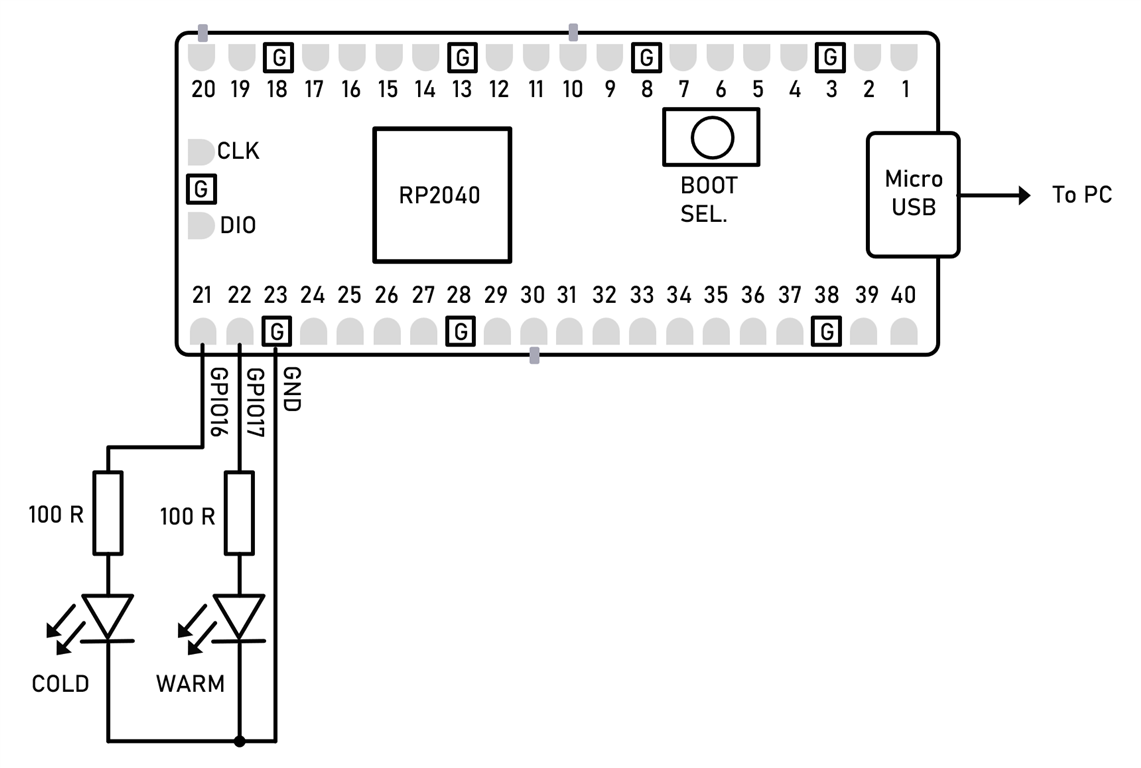
Any two LEDs can be used but ideally not white LEDs because they often require a voltage higher than 3.3V). You could use a couple of normal red LEDs at this stage.
Next, hold down the BOOTSEL button on the Pico, and insert the Pico USB cable into the PC. Release the BOOTSEL button. A USB memory drive letter will appear on the PC. Drag and drop the picochroma.uf2 ready-built firmware file onto the drive letter. The Pico will install the firmware into its Flash memory, and the code will begin executing.
Open a serial terminal (for instance use PuTTY) and connect to the USB serial port that will have appeared in the PC’s Device Manager (or equivalent with Mac/Linux).
Press the ‘h’ key to bring up a menu.
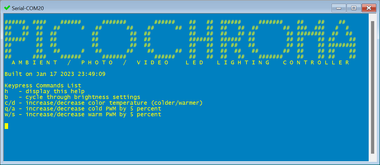
Now buttons can be pressed on the keyboard to experiment with the project. For instance, press the ‘c’ and ‘d’ keys repeatedly to shift the color temperature toward cold and warm colors respectively. The serial terminal will display some information as each button is pressed.
The PicoChroma source code can be edited and re-built; consult the Pico C SDK documentation to see how to do that, or alternatively check out one of the many blog posts on this topic on this site.
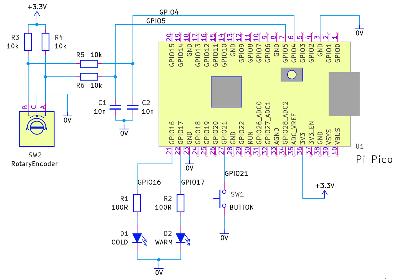
The circuit can be extended, and the same firmware will continue to work. The diagram below shows how to add a rotary encoder and a push button. With this circuit, the USB serial terminal menu no longer needs to be used. The push-button is used to toggle between the brightness adjustment mode and the color temperature adjustment mode.
The earlier test LEDs can be replaced with more useful cold and warm white LEDs using the following circuit modification (this still isn't a great circuit, but it is outside of the scope of this blog post for now to develop a better LED driver):
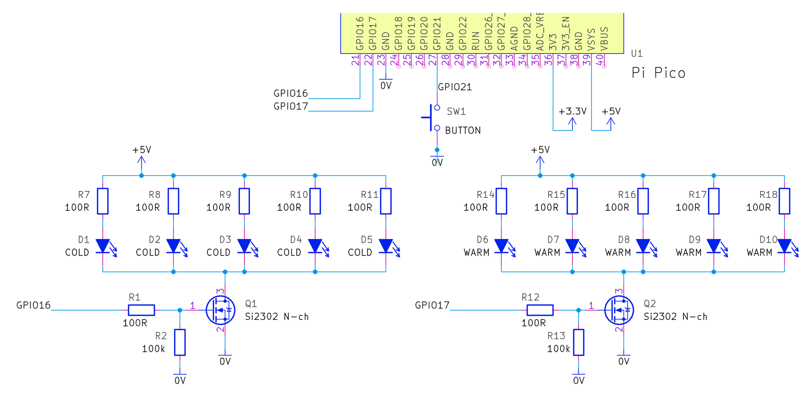
For the proof-of-concept, I used the following LEDs:
| Name | Description |
| Cree LM1-EWN1-01-N2-00001 | Cree LM1-EWN1-01-N2-00001 Cold White LED, 20mA |
| Cree CLM3C-MKW-CWAXB233 | Cree CLM3C-MKW-CWAXB233 Warm White LED, 20mA |
More advanced, and more powerful LED driving circuits could be connected to the two GPIO pins. It is not part of this blog post, because it is dependent on what’s required. If you want to use very high-power LEDs, drive a lot of LEDs, or want more efficiency for battery-powered systems, then a different circuit is needed. The circuit shown above could be fine for creating a small camera/video light, or for trying out the code before investing time in designing a better circuit. The circuit above makes no attempt to run from a stable source nor supply constant current identically across all the LEDs. It is simple and crude; I used the cheapest warm and cold LEDs that I could find for this initial prototype. For higher-end LEDs, I’d want to invest the time in a better driver circuit!
If you wish to display the brightness and color temperature values on a 7-segment LED display, then the following project can be added:
The rest of the blog post explains aspects of the project in more detail.
Color Temperature: What is it?
If an ideal black body is heated, it will glow with a color that varies depending on how hot it is. An incandescent light bulb is an approximate ideal black body, and the tungsten filament reaches temperatures of around 2400 Kelvin. The diagram below shows typical color temperatures for other situations; they are also known as correlated color temperatures (CCT) since it’s possible to create those colors without heating objects to these temperatures.

Ideally, the color temperature of a camera light ought to be similar to the existing ambient lighting. It therefore makes sense to have the ability to adjust color temperature for camera lights.
Although color temperature in Kelvin is a useful concept, it also makes sense to be able to map such colors to a different format; all possible colors of light of the same fixed brightness can be represented on a 2-dimensional chart, and therefore color temperatures can sit as a subset on such a chart.
The chart below is marked to show where 3000, 4000, 5000, and 6000 K values sit. The values are almost in a straight line (they are actually in a curve, more noticeable if lower and higher temperatures are also plotted, but for this small range it could be approximated by a straight line. The curve happens to be called the Planckian locus; the path that is traced in a color space by a black body heating up).
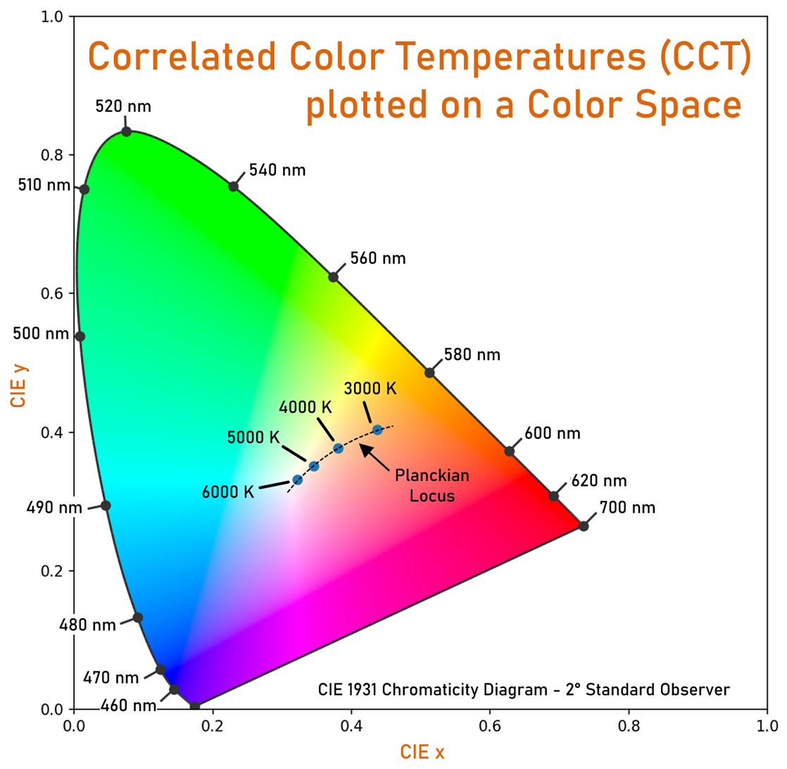
The interesting thing about this representation is that if any two points are selected and a straight line is drawn between them, then any color that sits on the line can be approximated by blending the colors at the two points! What this means is that if we pretend that those color temperature locations are in a straight line, then we can create the look of any color temperature in-between, from just two types of LEDs; warm-white LEDs and cold-white LEDs.
A better system would use additional LEDs because the color temperatures are not on an entirely straight line. Some modern camera lights use RGB LEDs, and they can (or rather, they should be able to) more closely represent the desired color temperatures.
Anyway, back to the problem at hand; how can color temperatures be converted to coordinates (they are known as chromaticity coordinates) on the color space? There are formulas for doing that, but I do not know about them, and I don’t think they are necessary, because it is just as easy to use a color temperature lookup table; the data will never change.
Blending Colors
The next question is, how can two LED colors be blended, and approximate color temperatures in between? I used a document called “Variable CCT constant illuminance white LED light communication system with dimming feature” by Das, Bardhan, Maity, and Mazumdar, which had the explanation.
See the code for the detail (the led_tables_init() function). The approach is to determine the chromaticity coordinates of the two LED colors (in my case by using the table mentioned earlier), called xw, yw, xc, yc in the code, and then, using only ratios, there is a derivation that the brightness ratio (called rem in the code) of the cold LED over the warm LED, is equal to the ratio rwc of weighting coefficients multiplied by the value ry which is the ratio of the chromaticity ordinates of the cold LED over the warm LED.
Once the ratio is determined, this can be translated into PWM duty cycle values, for the two LED types. If lower brightness at the same color temperature is desired, then the PWM duty cycle values can both be reduced by the same factor.
It stands to reason that something further needs to be done because, with this basic scheme, the maximum possible brightness won’t be the same for all possible color temperatures, because the duty cycle for any LED cannot exceed 1, and therefore the color temperature where the duty cycle is identical for both LEDs will be the one that can be set to the brightest level achievable with the LEDs.
To solve that, one strategy could be to limit the duty cycles so that all selectable color temperatures can have the same brightness levels. I decided to use that strategy because otherwise, it would be a pain if the user couldn’t adjust color temperatures without being assured that the brightness is not changing. If desired, in the future, a “boost” button could be available for the user to override the limit.
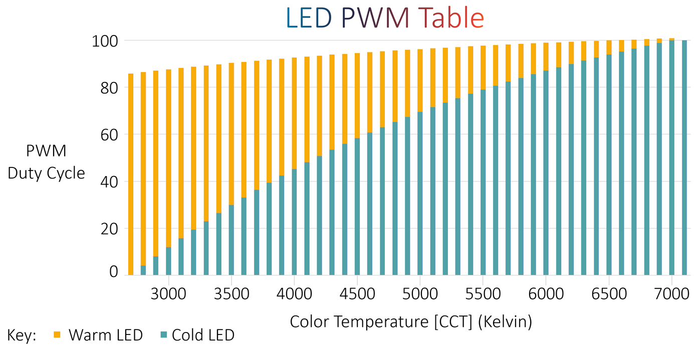
What does this all look like? The chart below (it is explained further below in this blog how such a chart can be created for any arbitrary LEDs) shows an example, using the particular LED models mentioned further above (i.e. Warm LED: Cree CLM3C-MKW-CWAXB233 and Cold LED: Cree LM1-EWN1-01-N2-00001).
The stacked column chart below shows the PWM duty cycle for those specific warm and white LEDs, in order to create white light of different color temperatures.
A few things can be observed from here, but in particular, it can be clearly seen that the warm LED never runs at 100% duty cycle, because (according to the datasheet, and as was shown in practice) the warm LED happens to be brighter.
Compile-Time vs Run-Time Calculations
Ordinarily, it can be desirable to do as much computation as possible up-front, so that the microcontroller doesn’t have to do as much. For this project, a different method was used, because the Pi Pico has a lot of power, and I wanted to make it easy for the user to change LEDs and to experiment and tweak. It would be a pain if the user had to calculate tables and upload them each time. Therefore this project just has a few configuration items in the source code, and the Pico will self-calculate the correct PWM values on-the-fly. The Pico will translate color temperatures into the color space coordinates, and then work out where the PWM needs to be for any desired and supported color temperature. Some lookup tables (constant arrays) are still used, but they are unrelated to LED parameters. There is also a built-in experimentation utility whereby the user can press keys in a terminal, to adjust the PWM settings without needing to recompile. Once the user is happy with the behavior of the LEDs, then the values can be placed in the code and compiled just once. Theoretically, the settings could be placed in Flash without recompiling, but I didn’t implement that. It’s not difficult to add that feature if it was ever required in the future.
Creating New Projects with PicoChroma
At a high level, all that is needed to use PicoChroma in lighting projects are three lines of code:
led_tables_init();board_init();set_lighting(module, color, brightness);
The parameters for the set_lighting function are:
module: Always set to 0. In the future, this could be set to different values, for controlling more than one lighting module
color: This is a value between 25 and 100, corresponding to the desired correlated color temperature (CCT) value between 2500 to 10000
brightness: This is a value between -1 and +9. The value -1 switches off the lighting. The value 0 is the dimmest, and the value 9 is the brightest. I didn’t feel the need to have more granular brightness capability but it could be implemented if desired.
The LEDs are pre-configured in the code using just four definitions:
#define CCT_W 3100#define CCT_C 6400#define EM_W 1.0#define EM_C 0.60
The CCT_W and CCT_C values are the color temperatures in Kelvin for the warm and cold LEDs respectively.
The EM_W and EM_C values are used to let the code know how bright the LEDs are relative to each other, and this can be worked out from the LED datasheets. If identical brightness LEDs are used, then both values can be set to 1.0.
The next section discusses how to refine these four values for more accurate lighting.
Calibration
I wondered, how could I check if the project was functioning successfully and if the color temperature rendering was accurate or not? Color meters and spectrometers are not everyday test tools for all, and at least I didn't have them. I wanted to have a calibration method that would allow one to find the values for the LED-related constants in the code, specifically:
The constants CCT_W and CCT_C which are the color temperatures in Kelvin for the warm and cold LEDs respectively.
The EM_W and EM_C values which identify how bright the LEDs are relative to each other.If identical brightness warm and cold LEDs were used, then both values can be set to 1.0.
In the end, I came up with a method that I’m convinced is providing results to decent accuracy. What I did, was simply use a normal photography camera to perform the measurement! I also tried my mobile phone’s built-in camera, which provides a fair approximation, but I think a photo camera is the way to go.
The procedure is actually very simple, although it looks like a lot of steps. The point of the steps below is to (1) first try to establish the color temperature of the two LED types, and (2) try to balance the brightness of the two LED types.
1: Establishing the Color Temperature of the LEDs
(a) Configure the PicoChroma code definitions for the LEDs as best as you know, so that the color temperatures of the warm and cold LEDs, and the approximate brightness relative to each other, is configured. It does not need to be accurate at this stage, and you can simply use the typical values in the LED datasheets (in my case, I used the values 2700, 6500, 1.00 and 0.60 for CCT_W, CCT_C, EM_W and EM_C respectively, for the LED part codes mentioned earlier). Build the code and upload it to PicoChroma.
(b) Power up the PicoChroma and set it to maximum brightness and minimum color temperature (i.e. as warm as possible; the cold LEDs will be fully extinguished);
(c) In a dark room, shine the PicoChroma LED array on a white sheet of paper
(d) Take a photo of the paper, with auto white balance, in the camera’s Raw Mode.
(e) Open up the raw file using a photo editor such as Adobe LightRoom or Phase One Capture One. Some cameras come with free photo editor software which might be suitable too.
(f) Use the White Balance tool (it often looks like an eye dropper/pipette icon) in the photo editor, to select a point on the paper. The white balance will now become corrected on the photo.
(g) Read off the white balance color temperature value from the software, and make a note of it. This value is equal to the color temperature from the PicoChroma LED array! In particular, it will be the color temperature of the warm LEDs, since the cold LEDs are extinguished as mentioned in step (b)
(h) Now set the PicoChroma to maximum color temperature (i.e. as cold as possible), and repeat steps c-g. By this stage, you now have two color temperatures written down, and they are the values for the warm and cold LEDs. Plug those values, rounded to the nearest 100, into the code definitions, re-compile it, and upload it to the Pico. In my case, the values I measured were 2730 and 7100, so I rounded to the nearest hundred and put the values 2700 and 7100 into the code definitions.
(i) Set the PicoChroma to maximum brightness as before, but now set the color temperature to a value other than maximum or minimum. In my prototype, the minimum and maximum were 2700K and 7100K respectively, and I set the PicoChroma to 3700K for this step.
(j) Again make a measurement of the color temperature using the camera and the photo editor software as before, and write down the value that was set on the PicoChroma, as well as the measurement.
(k) Repeat steps i-j for a few more data points. In my case, I obtained measurements at 4700 and 5700K. You can also obtain measurements for the minimum and maximum color temperature settings as well now if desired.
(l) By now, you will have values that you can write in a table that looks like this:
|
CCT Value on 7-Segment Display (Multiply by 100 for value in K) |
Value Measured |
| 27 | 2730 |
| 37 | 4250 |
| 47 | 5150 |
| 57 | 5800 |
| 71 | 7100 |
Now you can examine the results. As can be seen in the table above, the first and last values should be very similar between the dialed-in value on the 7-segment display and the value recorded by the steps above.
The other values however may have a larger discrepancy. The table above shows the real results I initially obtained.
Now you can try to correct the error. The thought process is, that the majority of the error now is likely to be because of brightness differences since the color temperature of the LEDs has been established and corrected for the minimum and maximum settings. This is the purpose of the second part of the calibration.
2: Correcting for Brightness Differences between the Warm and Cold LEDs
By looking at the table that was created in the first part of the calibration procedure, you can see that the measured color temperature value is greater than the value on the 7-segment display. For instance, the display indicates 3700 K when the measured value is actually 4250 K. This means that there is too much cold white light being added by the LEDs. To fix this, the hard-coded value for EM_C can be increased a bit, and then the calibration can be run again from step (i) onward. After a few iterations, I arrived at an EM_C value of 0.85, and the following results:
| CCT Value on 7-Segment Display | Value Measured |
| 27 | 2730 |
| 37 | 3830 |
| 47 | 4870 |
| 57 | 5650 |
| 71 | 7100 |
The error in Kelvin is just a few percent, so I stopped at this point. It is already more accurate than a fairly decent $200 LED light that I tested. There’s not much point trying to refine the values further, because I used cheap LEDs and there’s no guarantee they sit on the Planckian locus anyway. There’s no amount of correcting that can solve that. The solution is to use better LEDs or to use additional colors to steer the color temperature onto the locus.
Using a Color Checker
If you’re into photography then you may have a Color Checker type of tool, and it can be optionally used for a bit more accuracy. The procedure is broadly the same as above, except that instead of a sheet of paper, the color checker surface is photographed, and illuminated by your LEDs. Briefly, (the instructions vary depending on what you're using) follow the Color Checker tool’s instructions, which will require the photo to be saved in a particular format, and then the supplied Color Checker software will examine the image and build up a tool will build up a file called an ICC profile. Open up the same image in your photo editor (for instance Lightroom or Capture One), apply the profile, and then use the eye-dropper tool to select one of the grey-shaded squares, and then read off the color temperature value from the photo editor software. That value matches the color temperature of the LEDs, and then that value can be plugged into the PicoChroma code.

XML Format LED PWM Tables
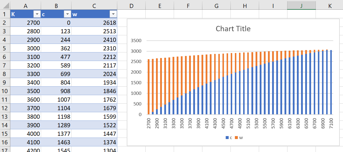
The chart in an earlier section above shows what duty cycle is used for the two LEDs, for different color temperature settings. If the configuration parameters mentioned earlier are changed, then of course the duty cycle settings will change, and it can be interesting to see that detail in a chart. Upon startup, PicoChroma will automatically dump its internally calculated PWM tables over the USB serial connection, if it is connected to a console/terminal software such as PuTTY.

The table is in XML format so that it can be easily imported into spreadsheet software (such as Excel):
(a) Copy the section highlighted in red and paste it into a text file, and save it to your PC (it must be saved with a .xml suffix)
(b) Create an empty worksheet in Excel, and then select Data->From Other Sources->From XML Data Import, choose the file, and click on OK if Excel mentions that it needs to create a schema.
(c) The data will appear in three columns; the first contains the color temperature values in Kelvin, and the second and third columns contain the PWM width values for the cold and warm LEDs respectively. Now it is easy to select the data and create any desired chart.
How was this Project Created?
This was my first ever project to be partially designed by AI.
I relied on two services to assist me; ChatGPT, and GitHub Copilot. They were used for different phases.
ChatGPT helped right at the start of the project, by providing me with high-level information on how to achieve different color temperatures using LEDs, because this was an entirely new topic for me, and it also helped with providing code that I used to manipulate some of the constants and data that were needed. The code from ChatGPT was not error-free, but it was a great start.
GitHub Copilot helped throughout the software development, directly offering me code suggestions and pretty much typing code lines for me as I worked, in real-time.
I reckon together, even on this short project, it saved me a day of work. It seems a no-brainer to use them. There’s a subscription fee for Copilot after the free trial period, but it is so low ($10 per month), it would pay for itself for the entire year with just a few days of usage.
Many software languages and development environments are supported for Copilot. For instance, following the Copilot instructions, I installed a plugin for it into CLion:

The example below shows what it’s like in action; I didn’t type a single character for the line highlighted in red, Copilot did. Copilot would regularly figure out what I was doing, and automatically offer lines of code, at least as good as I could manage, or better, and with the benefit of not making typo mistakes as I would.

Next Steps
I’d like to design a PCB for the project, but I need to think up a form factor for it. I’d also like to create a couple of different LED driver/LED array boards. It would also be great to add DMX capability to it. It would be awesome to hear about other people's ideas for the project, and if anyone has uses for it.
Summary
An adjustable color-temperature and adjustable brightness LED lighting system was developed for the Pi Pico, all ready for attaching to LED circuits. This is really only half a project without the LEDs! However, I think that’s something anyone interested in this can work on to suit their individual needs.
The calibration procedure ensures that regardless of which LEDs are used, the color temperature can be reasonably well controlled and matched against other lighting. The PicoChroma code and ready-built firmware are on GitHub.
Thanks for reading!

Top Comments