


As part of my Eclypse Z7: Zynq-7000 SoC Development Board - Review road test, I decided to try creating my own SYZYGY peripheral board. I've already documented my research into the Syzygy/Zmod ecosystem here and quickly designed a board to be sent off to one of the usual Chinese board houses for production. I have no particular affinity for any of them but decided to go for Elecrow this time and spun up a PCB with a black soldermask to go with the Eclypse Z7 and the Digilent Zmod boards.
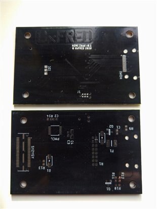
The PCBs are back!
I must admit I did the design in a bit of a hurry as I didn't want to wait ages for the boards and for this "part 2" of my road test to be too far removed from the first part. I needn't have worried. The boards were at my door with 10 days of ordering. Considering they only cost $11.58 and I received 10 boards rather than the 5 I ordered, I'm once again amazed at how good, cheap and quick it is to get your own board spun up.
I decided to put most of the components on the bottom of the board. The reason for this was that I intended to reflow the board in my toaster oven and thought it better to have all the surface mount components on the same side. The surface mount Samtec QTE connector has to go on the bottom, so I decided everything else would go with it and the top would be saved for the HDMI connector. This is of source also surface mount, but has some through hole lugs too.
This left a fair bit of empty space which I filled with a 0xFRED logo. It was fairly large as the letters are drawn with three PCB traces. I worried a little that it might be too overstated, but as they're traces under solder mask it was reasonably subtle. I think it came out fairly well. One thing I did notice is that I put "HDMI Zmod v0.1" on there and as I discussed in my previous post, this is not strictly a Zmod board as that would require some of Digilent's Zmod code. Oops. I'm hoping they don't sue me! 
Populating the board
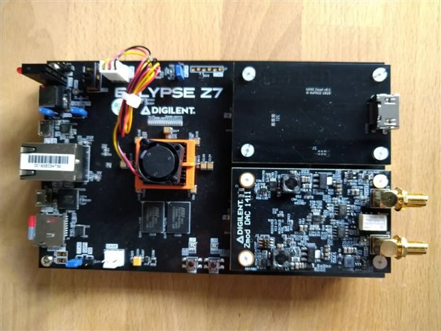
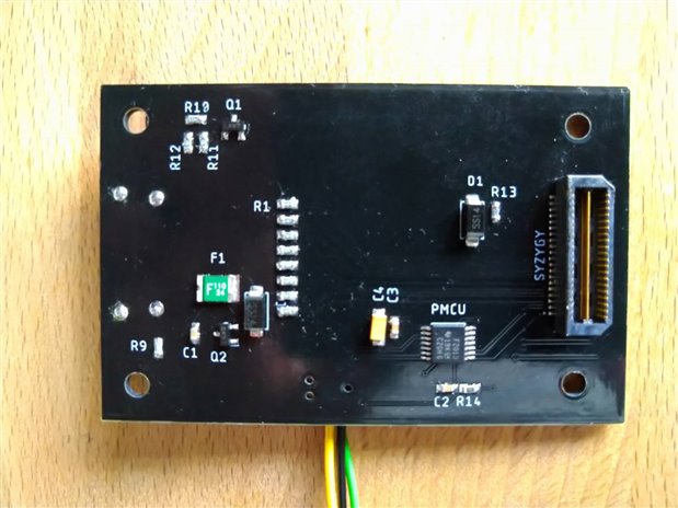
First things first, I populated one of the boards. I didn't use a stencil or reflow oven for the first one. I just added a few blobs of solder paste and got out the hot air gun. It all went OK. I needed some solder wick for the 0.8mm pitch Syzygy and HDMI connectors but all in all it wasn't too bad. I suppose I was most worried about some of the physical aspects. Did the syzygy connector and mounting holes match the Eclypse Z7? Does the HDMI cable foul anything? I needn't have worried about that. It was all fine. and looked nice mounted on the Eclypse Z7 alongside the Zmod DAC. I was wondering whether my choice to put the component underneath made it look a bit bare though. Those three wires are to let me spy on the I2C comms between the host board and my peripheral. Putting all the components on the bottom doesn't make it easy to debug. Strangely, this was the first board I've ever made without even a debug LED on it either! Luckily a sharp probe tip and those vias in the middle do the job.

Syzygy DNA
The first thing i decided to do was to sort out the I2C communication as required by the "Syzygy DNA" side of Syzygy. This is some reasonably simple communication to tell the host board things like what I/O voltage you need and what current you might draw. Here's where I hit a couple of small glitches.
Port identification
The first thing you need to do is to measure the voltage on the RGA pin of the Syzygy connector using the ADC of your microcontroller to find out what Syzygy port you're in. Unfortunately I missed a pull-up resistor on this. Not a biggie, but a minor error. Never mind. This resistor is used to let you know what I2C address to respond to. If I know I'm on port A I can just hard-code this for now.
I2C
In my hurry to spin up a board, I chose one of the first microcontrollers I even used - the little MSP430F2103. I checked it could do I2C and used the right pins, but what I forgot was that this tiny device uses IT's simplest USI peripheral. This means you need to handle a lot of the I2C work in software - the state machine for one thing. As the microcontroller is only dong one thing that's not too bad, but it did mean I had to dig out my old copy of MSP430 Microcontroller Basics and git down and dirty with low level I2C stuff. I found it more awkward that it should be and decided to also put this aside for now. All I seemed to manage was to interfere with the I2C comms for the Zmod in the other port. It didn't help that all the TI example code assumed it was the only device on the I2C bus.
I can see from the Eclyse Z7 schematic that the Syzygy port is connected directly to the Zynq pins, so I should be able to ignore these comms and quickly check that the wiring for the HDMI is right. Let's jump ahead a bit.
HDMI wiring
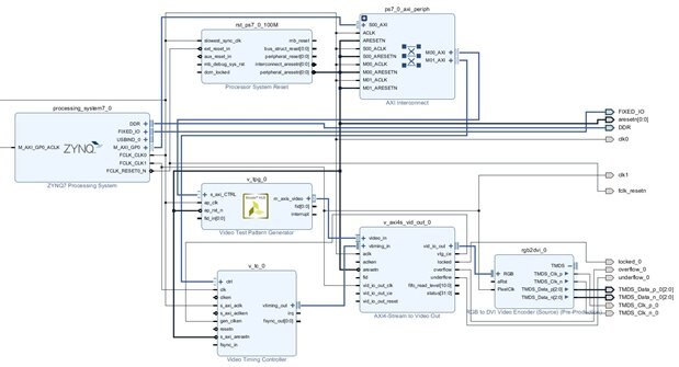
Whilst waiting for the PCBs I knocked up a test project that uses a pattern generator to output a test pattern over HDMI. I made sure this ran OK on the Pynq Z2 and ported it over with only minimal changes to go with the different pins connected to the HDMI socket. I fired it up and... nothing. I figured there was no point spending ages on the polish of I2C and Syzygy DNA if the hardware wasn't even right, so I spent quite a while on this. An embarrassingly long time, in fact.
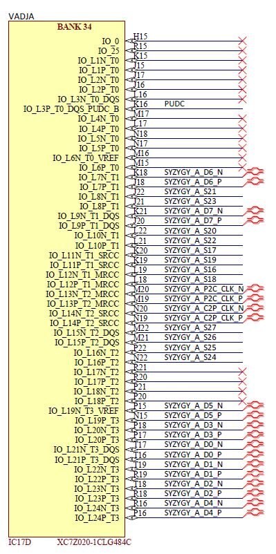
Nothing was coming out on the pins I'd connected to HDMI. I figured I must have made a mistake. I tested for ages, running PL clock signals and video timing flags out to the Pmod port so I could see what's happening. It was only when I moved one of these working test signal from the Pmod to the Syzygy port that I twigged what was happening. I knew I hadn't told Syzygy what IO voltage I needed but I hadn't realised that mattered. The IO bank used for this Syzygy port was driven from this voltage! Obvious now, but I hadn't realised they were externally powered. I assumed if my Vivado design was right then that was all that mattered. This tiny "VADJA" label at the top of the IO bank was the key!
Going back to the start and not missing bits!
So, now I realised that jumping ahead to test the hardware before finishing the I2C bit was a bit of a mistake. Don't rush stuff and do it in the right order!
Now I'm wondering if ignoring that pull up resistor might be borking the I2C address. Sure, I know the device is in port A, but maybe the host board also monitors the voltage to see if a board is physically present. If it's not pulled up then maybe it doesn't bother starting to talk over I2C!
Well, I'm making progress. So far it seems that Syzygy is a little more complicated than Pmod. I might have said unnecessarily complicated, but I'm starting to see that ignoring those complications may be biting me.
Update - Jan 2021. Syzygy DNA is finally working!
So, after months (on and off) of struggling with why my Syzygy DNA code wasn't working, I've finally got that bit cracked! My code would do odd things. It would work with the debugger plugged in, but not without. I'd make some small change and it would start working. I suspected I2C timing issues. I don't like things working but coincidence but at least I could now check some other part of the design. I'd come back to it the next day and it would have stopped working again. Really frustrating.
Anyway, it turned out the the solder paste underneath the big ground connection on that Samtec connector must have failed to reflow properly. My mistake for using a new brand of paste on a tricky design. I'd ruled this out earlier as my continuity checks using a DMM were OK. It turns out that the pressure from the DMM lead was enough to create a contact! The ground connection via my debug probe must have done the job too. Resting a hot soldering iron on the tab long enough to get some heat into the pads below (but not enough to melt the plastic) seems to have done the trick.
Finally my MCU can negotiate an IO voltage and a small LED on the host board lights up. Most whoops of excitement in electronics come from an LED being illuminated when previously it wasn't. This was no exception!
Now onto the important bit. HDMI....
Top Comments