


Previous blog posts of my MSOX3034T Road Test:
Keysight InfiniiVision MSOX3034T RoadTest | Unboxing & First Impressions
Keysight InfiniiVision MSOX3034T RoadTest | Analog Specs & Basic Functionality
Keysight InfiniiVision MSOX3034T RoadTest | Low Speed Analog Experiments
Keysight InfiniiVision MSOX3034T RoadTest | Digital Channels & Serial Decoding
Hello Everybody!
In this blog post I will show you I measured the Bandwidth and the Update Rate of the Keysight InfiniiVision MSOX3034TMSOX3034T mixed signal oscilloscope.
The methods used requires relatively inexpensive equipment, and can be applied to any oscilloscope.
1. Bandwidth Measurement
By definition, the Bandwidth of an oscilloscope is the frequency when the amplitude of the observed signal is attenuated by -3 dB. Or in other words, when the signal drops to ~70.7% of its original value.
In order to determine the bandwidth of an oscilloscope, we need measure the attenuation introduced by the probes and the acquisition pipeline of the scope at different frequencies.
To do this we can use a signal source with adjustable frequency, and known amplitude. Usually this would be a function / arbitrary waveform generator, but the ones capable of frequencies >= 350 MHz tend to be a little bit expensive.
So, I decided to use a relatively cheap Vector Antenna Analyzer, good for testing antennas from 137.5 MHz to 2700 MHz.

It has a mode for testing antennas at a fix frequency. After some testing, it turned out that in this mode the device outputs (kind of a) sine wave with a peak-to-peak amplitude of 100mV.
I used this antenna analyzer to generate sine waves at different frequencies, and measure the attenuation introduced by the scope.
To measure the attenuation I added a Peak-to-Peak measurement with Statistics, and I noted the mean Pk-Pk values. As the signal was a little bit noisy, I though to also add AC Rms measurement.
So, here are the measured values:
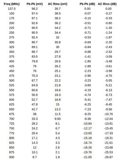
From the voltage values, I calculated the the attenuation in dB.
Here is a plot of the attenuation introduces by the scope:

The -3 dB point is reached was reached at about 470-475 MHz, so that looks to be the actual bandwidth of the scope. This is about +35% higher then the guaranteed spec of 350 MHz.
I also made a short video about how the measurement was done:
It would be also interesting to take on what the bandwidth measurement looks on the 500 MHz model. The 350 MHz and 500 MHz models are basically the same hardware, the difference being a software license.
2. Update Rate Measurement
The Update Rate of an oscilloscope usually can be directly measured by measuring the frequency of TRIG_OUT output using a frequency counter.
As I did not have a dedicated frequency counter, as started looking for alternatives.
The scope has a built-in frequency counter, so I first though to use that one. Unfortunately, for reason, the scope did not really liked when I connected TRIG_OUT output to one of the input channels. The amplitude TRIG_OUT signal was too low, and there were also some artifacts at around the trigger point.
After some searching, I remembered that my multimeter has a frequency counting function, and it is good up to about 10 MHz.
So, I hooked it up to the TRIG_OUT signal and started taking some measurements:

The input signal was 20 MHz sine wave generated using the built-in function generator.
I took measurements in different Time Division setting, from 2 ns / div up to 200 ms / div.
As I knew that the channels 1 and 2, and 3 and 4 share some of the acquisition, I decided to also took some measurements with 2 channels (1&2) enabled, instead of just one (1) channel. I also played with setups using alternating channels, three and four channels, but it does not makes much a difference compared to having just one or two channels enabled from the same group
I noted the measured values in the bellow table (first 3 columns):

From the measured values, I derived some other statistical value (that may or may not be relevant  ):
):
- Acquisition Time - Time Division x 10 (# of division on the screen)
- Dead Time - Total Update Cycle minus the Acquisition Time
- Acq/Dead Time ratio
- Theoretical Max Update rate
(most of the values are calculated both for the single and dual channels measurements)
So, here is what the Update Rate of the scope looks like in relation to the Time Division setting:

The maximum update rate of 1.104M wfms / sec is reached at the 10 ns / div setting, with similar values at 2 ns, and 5 ns / div settings. From there the update rate decreases linearly with the Time Div setting, except for some anomaly happening at around 50 uS / div.
Using two channels from the same group decreases the update rate by about ~30% at the lower Time Div settings. For above 100 ns / div, it does not seem to matter.
The next plot shows the calculated dead time of the scope in different setting, and as well the ratio between the acquisition and dead time:

Interestingly, the dead time (or blind time) of the scope is not constant, but it is increasing with the Time Div setting, from ~1uS to 100ms. Also, there is a weird anomaly at 50 uS / div, where looks like the scope switches to an other mode of operation
The measurement data from the two experiments are available in the following Google Sheets document:
https://docs.google.com/spreadsheets/d/1q1NWjrEnboWmSe3N7tYMVSfy7ZiUUVYZRmkPZxdDryE/edit?usp=sharing
Hope you enjoyed this post! 
Top Comments