element14 Community
element14 Community
    Register Log In
  • Site
  • Search
  • Log In Register
  • Members
    Members
    • Benefits of Membership
    • Achievement Levels
    • Members Area
    • Personal Blogs
    • Feedback and Support
    • What's New on element14
  • Learn
    Learn
    • Learning Center
    • eBooks
    • STEM Academy
    • Webinars, Training and Events
    • Learning Groups
  • Technologies
    Technologies
    • 3D Printing
    • FPGA
    • Industrial Automation
    • Internet of Things
    • Power & Energy
    • Sensors
    • Technology Groups
  • Challenges & Projects
    Challenges & Projects
    • Design Challenges
    • element14 presents
    • Project14
    • Arduino Projects
    • Raspberry Pi Projects
    • Project Groups
  • Products
    Products
    • Arduino
    • Dev Tools
    • Manufacturers
    • Raspberry Pi
    • RoadTests & Reviews
    • Avnet Boards Community
    • Product Groups
  • Store
    Store
    • Visit Your Store
    • Choose Another Store
      • Europe
      •  Austria (German)
      •  Belgium (Dutch, French)
      •  Bulgaria (Bulgarian)
      •  Czech Republic (Czech)
      •  Denmark (Danish)
      •  Estonia (Estonian)
      •  Finland (Finnish)
      •  France (French)
      •  Germany (German)
      •  Hungary (Hungarian)
      •  Ireland
      •  Israel
      •  Italy (Italian)
      •  Latvia (Latvian)
      •  
      •  Lithuania (Lithuanian)
      •  Netherlands (Dutch)
      •  Norway (Norwegian)
      •  Poland (Polish)
      •  Portugal (Portuguese)
      •  Romania (Romanian)
      •  Russia (Russian)
      •  Slovakia (Slovak)
      •  Slovenia (Slovenian)
      •  Spain (Spanish)
      •  Sweden (Swedish)
      •  Switzerland(German, French)
      •  Turkey (Turkish)
      •  United Kingdom
      • Asia Pacific
      •  Australia
      •  China
      •  Hong Kong
      •  India
      •  Korea (Korean)
      •  Malaysia
      •  New Zealand
      •  Philippines
      •  Singapore
      •  Taiwan
      •  Thailand (Thai)
      • Americas
      •  Brazil (Portuguese)
      •  Canada
      •  Mexico (Spanish)
      •  United States
      Can't find the country/region you're looking for? Visit our export site or find a local distributor.
  • Translate
  • Profile
RoadTests & Reviews
  • Products
  • More
RoadTests & Reviews
Blog Microchip CAN Analyzer Road Test - part 4: Analyze the Physical layer of CAN Bus
  • Blog
  • RoadTest Forum
  • Documents
  • RoadTests
  • Reviews
  • Polls
  • Files
  • Members
  • Mentions
  • Sub-Groups
  • Tags
  • More
  • Cancel
  • New
RoadTests & Reviews requires membership for participation - click to join
  • tcand332
  • microchip
  • mcp2551
  • automotive
  • protocol
  • hercules
  • can
  • Subscribe by email
  • More
  • Cancel
  • Share
  • Subscribe by email
  • More
  • Cancel
Related
Recommended

Microchip CAN Analyzer Road Test - part 4: Analyze the Physical layer of CAN Bus

Jan Cumps
Jan Cumps
17 Feb 2019

I'm reviewing the Microchip CAN Analyzer for a Road Test.

I'm now testing it in a CAN Bus test bed that I designed.

image


In the previous posts for this review, I've used the digital side of the CAN circuit.

I always had the intention to also test the physical layer. I built CAN driver breakout boards for that.


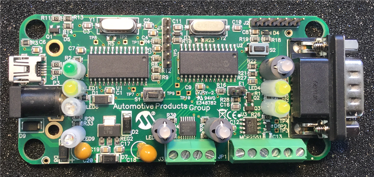
The Microchip CAN Bus AnalyzerMicrochip CAN Bus Analyzer supports both logic and physical side of the design.

You can plug it directly into a vehicle and check the traffic. There's an MCP2551 CAN driver on board.

It also allows you to check on the digital level (don't exceed 5 V) - valuable for firmware designers that don't need a CAN text fixture.

I've used that in all previous posts in this series.


image


But now, let's look at that physical layer.


image


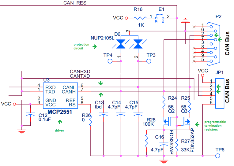
The CAN analyzer implements a protection circuit similar to what I did on the CAN breakout boards.

I use a different CAN driver, TI TCAND332D, but my circuit is virtually identical:

image


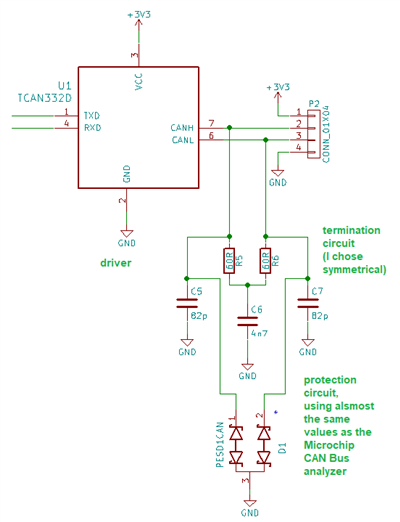
You can either use the DB9 connector or the screw terminal block to connect GND, CAN H and CAN L between the test circuit and the analyzer.

It's also interesting to attach an oscilloscope. Both H and L signals are referenced to ground, so you can put one channel to the H signal and the other to the L.

You'll see that both are positive signals, but inverted, around a midpoint that - in my case, is 1.85 V (see capture below)

The H signal will move between that midpoint and 2.8 V, the L between the midpoint and 0.9 V. So both have an amplitude of 0.95 V.

But they are opposite (differential) around that point.

image


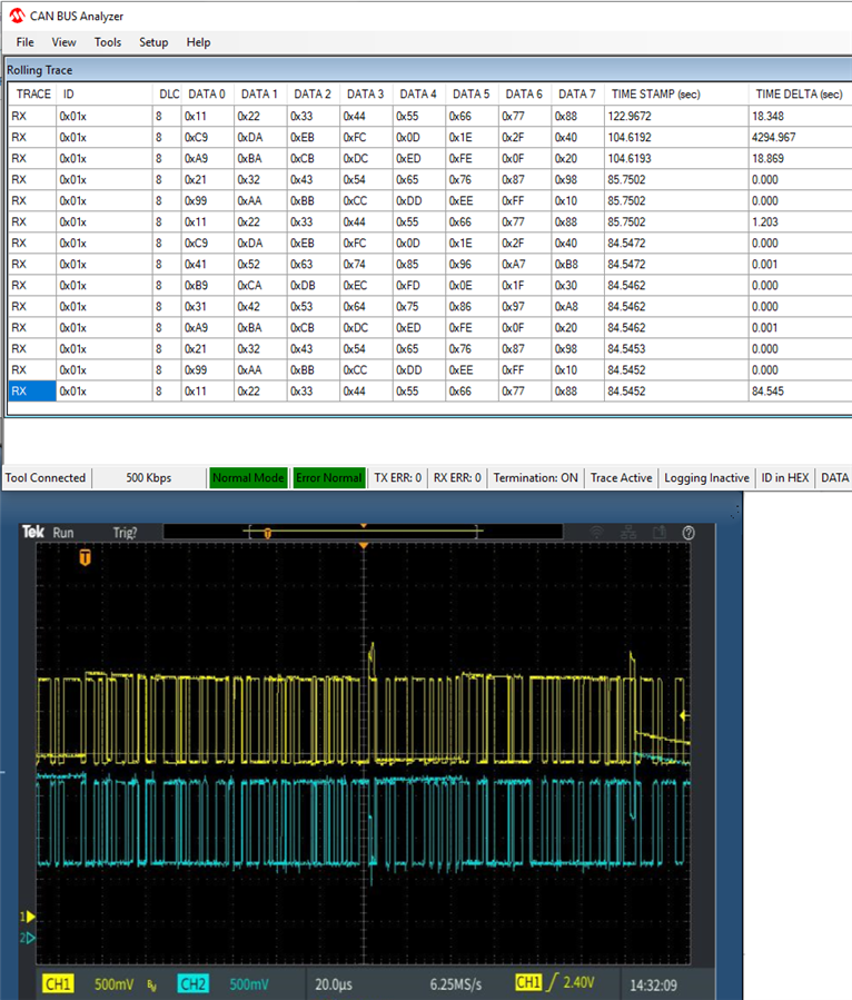
The Microchip CAN Bus analyzer behaves exactly the same when probing the digital or physical layer.

That's of course a good thing. The protocol is identical on both sides.

And I knew the analyzer was up to the task, because mcb1 had already tested that.


Now that I have the mini CAN network here at home, the analyzer can help me in real world designs.

For more info about my review and the test bed development, check:


Road Test Blog
part 1: First trials
part 2: Inject CAN Messages
part 3: Analyzer as Test Tool
part 4: Analyze the Physical layer of CAN Bus
Related Blog
part 1: tryout
part 2: Communication between 2 Devices
part 3a: Design a Bus Driver PCB
part 3b: Design a Bus Driver PCB - Schematics and Custom Components
part 3c: Design a Bus Driver PCB - Layout
part 3d: Design a Bus Driver PCB - Test
  • Sign in to reply

Top Comments

  • Jan Cumps
    Jan Cumps over 3 years ago +1
    I've set up a test bed to try out the Arduino MKR CAN shield I got from e14. On the breadbord, you see the Arduino CAN setup in front. Behind that, the 2 CAN driver boards I made for this road test, driven…
  • Jan Cumps
    Jan Cumps over 3 years ago in reply to Jan Cumps +1
    Well, that's a promising start. The Receiver example detects the traffic: All the traffic at the moment. I still need to set it up to select messages in scope.
  • Jan Cumps
    Jan Cumps over 3 years ago in reply to Jan Cumps

    Well, that's a promising start.

    The Receiver example detects the traffic:

    image

    All the traffic at the moment. I still need to set it up to select messages in scope.

    • Cancel
    • Vote Up +1 Vote Down
    • Sign in to reply
    • More
    • Cancel
  • Jan Cumps
    Jan Cumps over 3 years ago

    I've set up a test bed to try out the Arduino MKR CAN shield I got from e14.


    image


    On the breadbord, you see the Arduino CAN setup in front. Behind that, the 2 CAN driver boards I made for this road test, driven by a TI Hercules microcontroller.

    The black box behind the breadboard is the Microchip CAN bus analyser. The scope in the back shows the CAN bus' Hi and Lo differential signals.

    On the laptop I'm running the software for the Microchip analyser. It shows latest message (top window) and a rolling log of every message discovered (bottom window).


    The current setup only sends messages that are intended for the Hercules.

    Next steps are to create a CAN mailbox for the Arduino, try to make it retrieve those messages, then make it send messages to the other 2 CAN points ...

    • Cancel
    • Vote Up +1 Vote Down
    • Sign in to reply
    • More
    • Cancel
element14 Community

element14 is the first online community specifically for engineers. Connect with your peers and get expert answers to your questions.

  • Members
  • Learn
  • Technologies
  • Challenges & Projects
  • Products
  • Store
  • About Us
  • Feedback & Support
  • FAQs
  • Terms of Use
  • Privacy Policy
  • Legal and Copyright Notices
  • Sitemap
  • Cookies

An Avnet Company © 2023 Premier Farnell Limited. All Rights Reserved.

Premier Farnell Ltd, registered in England and Wales (no 00876412), registered office: Farnell House, Forge Lane, Leeds LS12 2NE.

ICP 备案号 10220084.

Follow element14

  • Facebook
  • Twitter
  • linkedin
  • YouTube