Hello everyone.
Last week I completed my participation in Experimenting with Current Sense Amplifiers Design Challenge. So, it is time to change something completely different.
Do you remember (last) Summer of FPGA? I do. There were multiple activities related to FPGAs and especially there were lot of possibilities to get FPGA devboards for free (for time spent by writing review) by applying for RoadTest. Last summer (2021) I was interested in FPGA RoadTests and I selected one of the offered RoadTest – Microchip PolarFire FPGA Eval Kit. I was successfully selected as a one of the official RoadTesters but unluckily due to some supply chain issues this RoadTest never started. This was quite sad to me, because this was the most powerful and complex FPGA from the offer. Later It was announced that element14 would get these Kits at the end of February (2022), but as you have seen February was past and we heard nothing about kits. Next postponing was set to April (2022), but April is also over and three weeks ago we received email that next estimation is set to October (2022) which resulted to final cancelation of RoadTest. But last week things changed dramatically and I received email, that Kits arrived to the Chicago Element14 office and originally selected RoadTesters were asked if they are available to do RoadTest. I agreed and today I received it!
In this first blog post I will show some of my first feeling with this extremely powerful FPGA evaluation kit.
Unboxing
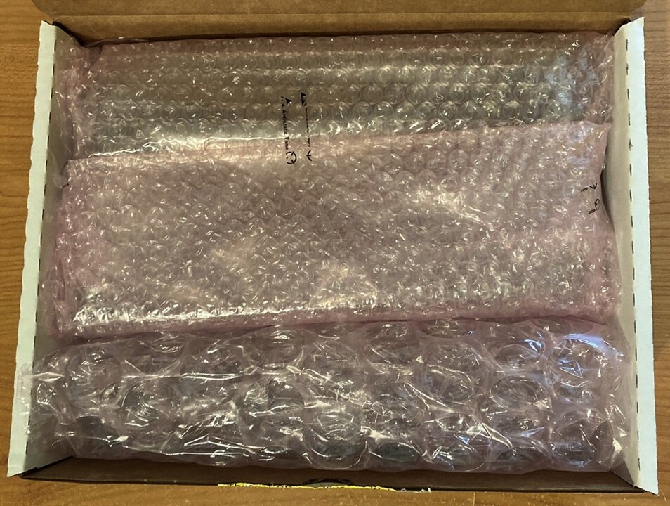
Kit come in white non-branded box with ESD sensitivity warning. Box was filled with lot of bubble foam protecting the very expensive content of the box:
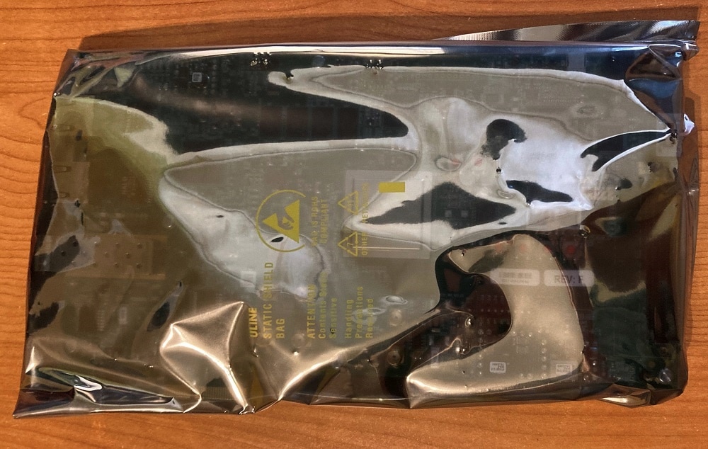
After removing first two layers of foam I have first time seen main hero of this RoadTest. It was packed in another antistatic bag:
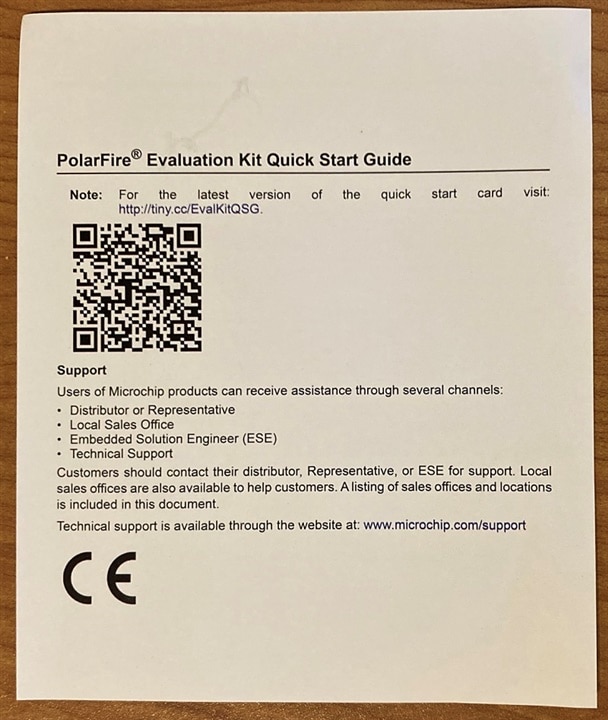
Except packed FPGA there were small letter with link to online version of Quick Start Guide.
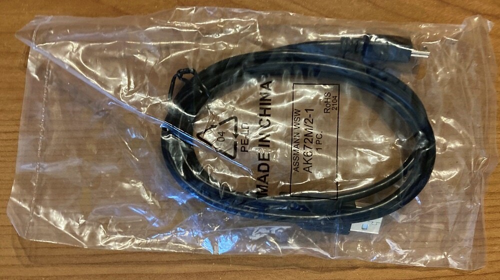
There were also USB to USB mini cable which is used for connecting board with PC:
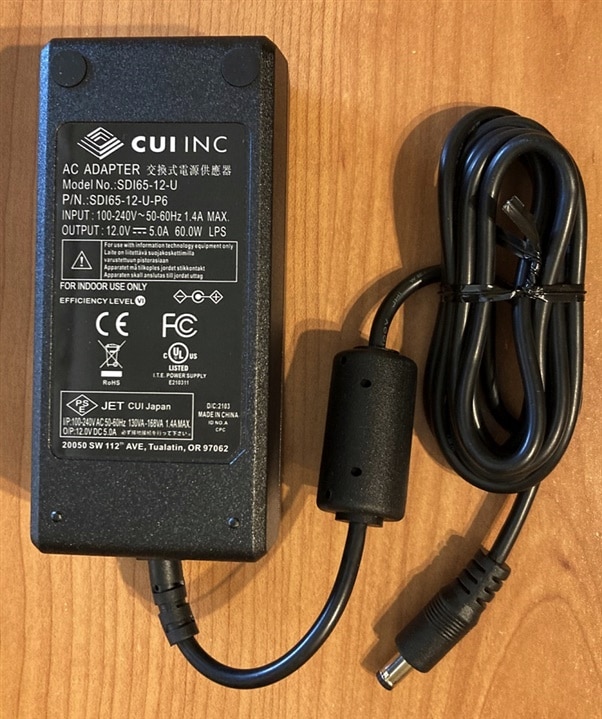
Package also contained 12V/5A power adapter:
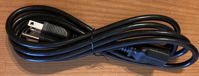
And finaly, last thing in the package is power cord for power adapter. I am not sure if microchip distinguish between USA and Europe customers, but I received power cord for USA outlets which is incompatible with outlets used in Europe. Package come from Element14 office in Chicago, so it is possible that Microchip ship European outlet if you order kit from Farnell instead of Newark. For me it was not a significant issue because power adapter itself accept both voltages and I found compatible power cord with European plug in my box containing unused cables.
And now, let’s look to the unpacked FPGA Eval Kit:
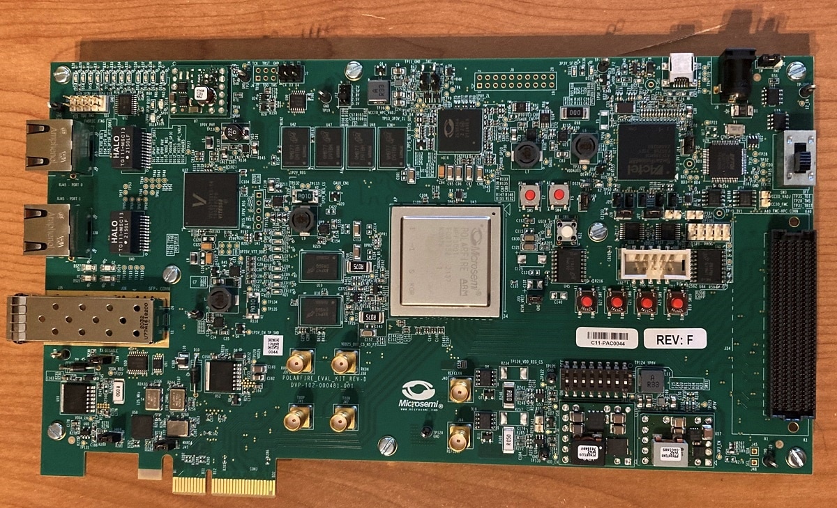
This board is quite large, FPGA is large. It is professional FPGA targeting many professional project. Main features of this board and FPGA are high speed interfaces. There are two 1 Gigabit ethernets, SPF+ cage, PCIe Express, FMC connector for connecting expansion boards, two types of DDR memory (DDR3 and DDR4), flash memories, secondary FPGA for power consumption monitoring and many more. There are tens of jumpers, LEDs, buttons, connectors, power regulators and so on.
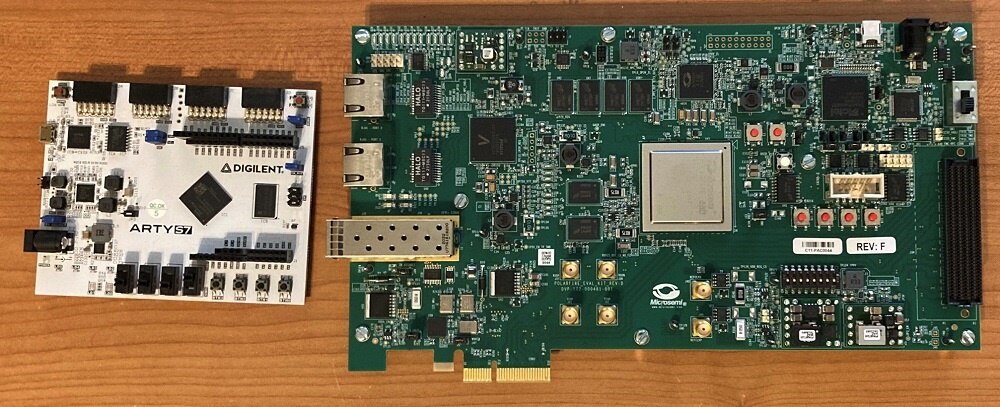
In the meantime of waiting for the (almost cancelled) RoadTest I applied for 7 Ways to Leave Your Spartan-6 FPGA and received Arty-S7 board recently. But now my Arty-S7 board look like poor sibling. They are completely different grade (hobby vs professional) and any comparisons of these two boards are totally misleading.
First design
In the meantime, of waiting for package shipment by UPS, I installed Libero SoC development environment and started to prepare, synthetize and implement my first simple design. Board was preprogramed with some demo utilizing LEDs and button (any maybe some more, but I did not test connecting Ethernet, PCIe and so on at this time), but I of course attempted to “run” my own Verilog code. I created following Verilog code for blinking onboard LEDs:
module top(input wire clk, input wire rst, output reg [7:0] leds);

    reg rst1;
    reg rst2;

    reg [23:0] tmr;

    always @(posedge clk) begin
        rst1 <= rst;
        rst2 <= rst1;

        if (rst2 == 0) begin
            leds <= 0;
            tmr <= 0;
        end else begin
            if (tmr <= 500000) begin
                leds <= 1;
                tmr <= tmr + 1;
            end else if (tmr <=  1000000) begin
                leds <= 2;
                tmr <= tmr + 1;
            end else if (tmr <= 1500000) begin
                leds <= 4;
                tmr <= tmr + 1;
            end else if (tmr <= 2000000) begin
                leds <= 8;
                tmr <= tmr + 1;
            end else if (tmr <= 2500000) begin
                leds <= 16;
                tmr <= tmr + 1;
            end else if (tmr <= 3000000) begin
                leds <= 32;
                tmr <= tmr + 1;
            end else if (tmr <= 3500000) begin
                leds <= 64;
                tmr <= tmr + 1;
            end else if (tmr <= 4000000) begin
                leds <= 128;
                tmr <= tmr + 1;
            end else begin
                leds <= 0;
                tmr <= 0;
            end
        end
    end

endmodule
After writing this code I integrated it to the blog design:

Then I assigned pins in I/O editor:

And complete whole chain of tasks required to build the circuit (synthesis, place and route, timing verification, power verification and bitstream generation). Then I attempted to program the board and it works as expected:
RoadTest Goals
The reason why did I applied for this RoadTest is that I want to try high-speed advanced interfaces. I want to try implement HW accelerated packet monitoring (and possibly even HW accelerated filtering) using this board and I also want to learn details about PCIe bus and do some high-speed data transfers between my computer and board. As part of RoadTest I will also point to other features of the board and the FPGA, and I especially want to target differences between competing FPGAs from other vendors (especially Xilinx because my skills with other vendors are limited).
Before posting final review, I will post some blogs or tutorials. I have not exact idea about topics, but I have some plans imagined. For now, I go learning this new toy. Stay tuned to my next blog posts and then to the final RoadTest review. Thank you for reading this blog post. If you have any question, feel free to ask in comments below.
