


Part A of the Bench Tests reviewed the performance of the auxiliary functions on the insulation tester and found them all to be well within the specified tolerances. In this second part of the Bench Tests, I will concentrate exclusively on the insulation testing function.
The MIT420/2 has five fixed voltages of 50V, 100V, 250V, 500V and 1000V and then a variable output function from 10V up to 1000V. This is not a voltage ramp function, the output voltage is set in the settings menu to the desired level and the function switch turned around to the variable voltage function to initiate the test. A desired change in the voltage level means that the user has to go back to the settings menu to adjust the voltage and then back to the variable voltage function again to carry out the test. The instrument will remember the last voltage setting even after it has been switched off. However, it reverts back to the default 10V if the batteries are removed.
For the purpose of testing an insulation meter, I have a bespoke insulation tester calibration box from Time Electronics. I carry this box around with me when I go to a site to verify that the insulation tester is function correctly before carrying out the tests on generator rotors, mainly due to the value of the rotor and the costs involved in carrying out the tests. This instrument has the ability to measure the open circuit voltage, the short circuit current and then apply a range of high voltage resistors across the instrument via 4 decade switches to verify the resistance readings from 10MOhm up to 90GOhm. I also carried out an extra test to verify that each insulation test range could output a 1mA current and maintain the specified voltage level as specified in the BS EN 61557 standard.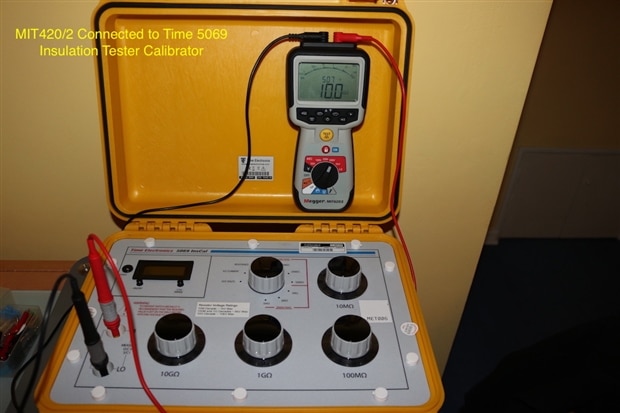
The calibrator has 4mm safety sockets to plug the insulation tester leads into, but unfortunately due to the ridge on the Megger leads, I had utilise an uninsulated 4mm adapter to allow them to connect to the calibrator. Nothing more than a slight inconvenience, but one example of the disadvantage of the test lead approach by Megger.

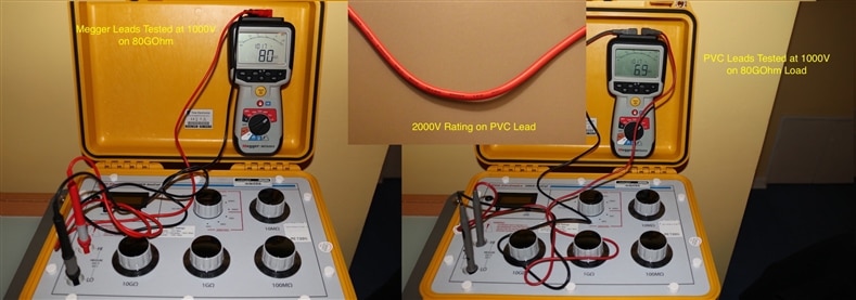
Despite this, the leads offered by Megger are of excellent quality and to show this I set up the calibrator to an 80GOhm load and tested the insulation tester against this using both the Megger test leads and the test leads I have from a multimeter. These leads are rated at 2000V but are manufactured from PVC and a lower quality.
The leads were set up twisted together, which is a poor test set up, but is being done to illustrate the quality of the Megger test lead set. The insulation tester was set up to 1000V for each test.
With the Megger test lead set a reading of 80GOhm was achieved and was found to be stable. With the PVC set, the reading was found to be much lower and quite erratic. It ended up as 6.9GOhm which is a significant difference to the 80GOhm setting on the calibrator. This kind of behaviour would seriously impact on the DAR and PI ratio tests the MIT420/2 is capable of carrying out.
The outcome is, if you use alternative test leads to the Megger set, ensure they are good quality silicone leads and pay attention to the test set up.
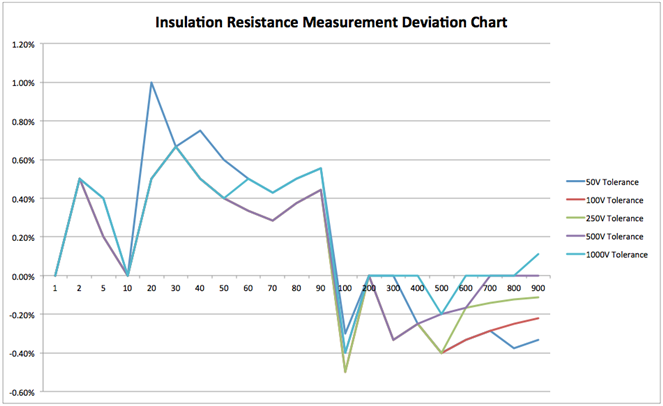
On to some insulation testing! The MIT420/2 has a base tolerance of +/-3% +/- 2 digits with an additional % tolerance per MOhm or GOhm dependent upon the resistance value and the range. To test the insulation accuracy each range of the instrument was tested against each decade value. The table below details the results found and the chart summarises the range of deviation seen from the actual resistance applied. All readings found to be significantly better than the base tolerance values with an overall deviation of +1% to -0.5%.

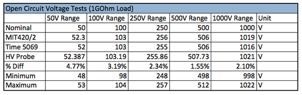
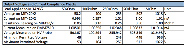
The next few tests were based around determining the performance of the measurement process for the insulation resistance. The first aspect was to measure the open circuit voltage of the instrument for each testing range. To do this, the output of the MIT420/2 was connected to a high voltage probe with a 1GOhm input resistance. This is done to reduce the load on the output of the insulation tester and allow the voltage to rise to its highest. If the output of the MIT420/2 was connected directly to a DC multimeter or bench meter it would have a 10MOhm load applied to it, that would increase the current being drawn and lower the output voltage.
The manufacturer specifies the voltage output to be between 0% and +2% + 1 digit. The results in the table show that the voltage output remained within specifications. The first test was carried out using the Time Insulation Calibrator but as the voltmeter on this only has a tolerance of 1%, the tests were repeated with the HV Probe and a bench meter that gave an overall tolerance of 0.15%. It was interesting to see that the instrument drifts further from the nominal voltage values at the lower end, but tends towards a tighter tolerance as the output voltage is increased. This is typical of insulation testers I have used over the years.
The circuit voltage tests are then repeated with a 1mA load applied to each range. As can be seen in the table below, the increased load on the output reduces the voltage closer to the nominal values but at no time did the voltage drop below the nominal values.
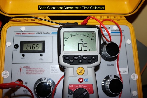
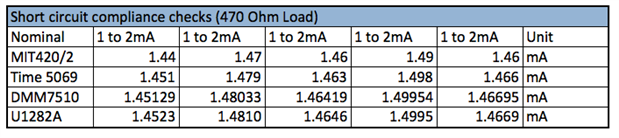
The next test was to verify the short circuit current capability of the unit. The standard permits a maximum output current between 1mA and 15mA, typically instruments of the type have an output of around 1.5mA and Megger specify the short circuit current to be between 1mA and 2mA. The tests conducted showed this to be the case. Whilst carrying out the tests, the uA-s-V function switch can be used to cycle the secondary display through to read the output current.
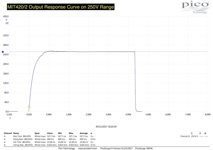
I then carried out a response test of the output by monitoring the voltage with a Picoscope 3404A via a high voltage probe. Due to the input voltage limitation of the Picoscope, the measurement was made via the high voltage probe, utilising a custom probe setup within the Picoscope software to create the correct voltage range. This test was done more out of interest rather than determining if the meter was performing to a specification. The results can be seen in the table below alongside a photo of the setup utilised.
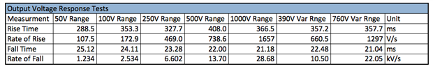
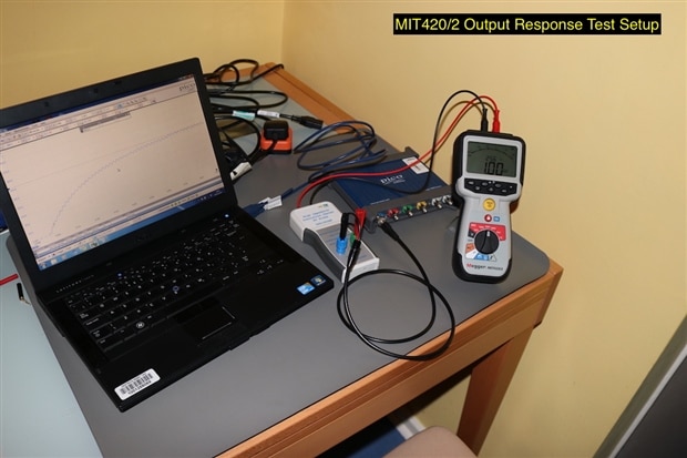
The rise time of the output varied dependent upon the voltage range, except for the variable output range that was tested at 390V and then 760V with both returning a comparable rise time. The fall time on each range was similar each time, between 20 to 25ms. A sample plot can be seen below on the left that shows the voltage rise as the test button is operated. A small overshoot is occasionally seen, but it is small and causes no concern. The plot on the right shows the ripple of the output by zooming in on the waveform.

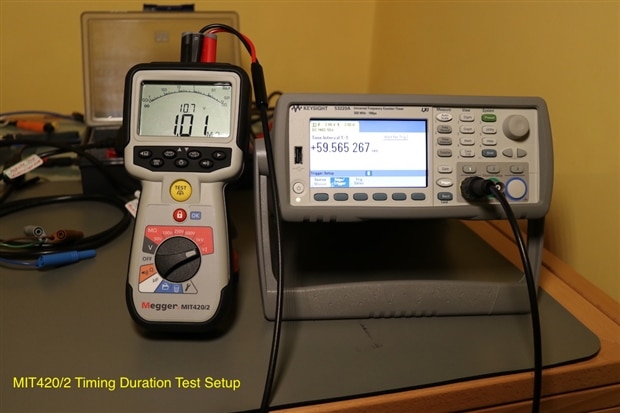
The final element of the test was to verify the accuracy of the timed tests offered by the MIT420/2. Three types of timed test are offered, the first is a simple duration test that is set between 1 to 10 minutes in 1 minute intervals in the settings menu. There is no duration shorter than 1 minute, which could have been useful for testing portable appliances or simple checks on smaller motors and transformers.
The second type of timed test is a dielectric absorption ratio (DAR), this is the ratio of the 60 second value divided by the 30 second value and is a representation of the quality of the main insulation as the applied voltage charges the circuit similar to a capacitor. A good insulation system will have a DAR ratio above 1.2.
The final timed test is a polarisation index (PI) which is the 10 minute value divided by the 1 minute value. This is more of a measurement of leakage current over the insulation surface mainly affected by moisture and dirt. For a Class F insulation system a ratio value above 2 is acceptable.
Not all apparatus will have a DAR or a PI ratio, it depends on the type and construction, hence why Megger have added a starlight timed test function. The IEEE 43 standard for AC and DC dielectric testing also advises that when a 1 minute insulation value exceeds 5GOhm, the DAR and PI values may not be representative of the insulation condition.
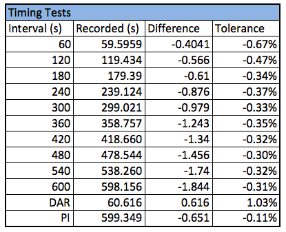
To measure the time function, I utilised the variable voltage test function, setting it to its minimum of 10V. This was applied across the input of a counter / timer unit set to the interval function. The manufacturer, does not specify a tolerance for the time function, so this was also done more out of interest. The values determined were all within 1% of the nominal value. Interestingly, the timed function gave values less than the set duration where as the DAR function always gave a time duration slightly over the 1 minute. Due to the instrument operation and the test setup on the DAR and PI tests, only the final 1 minute and 10 minute values can be recorded.
This concludes this blog on the insulation resistance bench tests. Throughout, the instrument performed flawlessly, it gave accurate results and had a fast response. The display is crisp and clear to read. Adjustment of voltage output and timing durations was easy to carry out and switching them to the setting menu means that they would not get adjusted easily by mistake.
In the next blog, before I take the instrument out into the field, I will review some of the safety features that have attracted my attention.
Top Comments