element14 Community
element14 Community
    Register Log In
  • Site
  • Search
  • Log In Register
  • Community Hub
    Community Hub
    • What's New on element14
    • Feedback and Support
    • Benefits of Membership
    • Personal Blogs
    • Members Area
    • Achievement Levels
  • Learn
    Learn
    • Ask an Expert
    • eBooks
    • element14 presents
    • Learning Center
    • Tech Spotlight
    • STEM Academy
    • Webinars, Training and Events
    • Learning Groups
  • Technologies
    Technologies
    • 3D Printing
    • FPGA
    • Industrial Automation
    • Internet of Things
    • Power & Energy
    • Sensors
    • Technology Groups
  • Challenges & Projects
    Challenges & Projects
    • Design Challenges
    • element14 presents Projects
    • Project14
    • Arduino Projects
    • Raspberry Pi Projects
    • Project Groups
  • Products
    Products
    • Arduino
    • Avnet Boards Community
    • Dev Tools
    • Manufacturers
    • Multicomp Pro
    • Product Groups
    • Raspberry Pi
    • RoadTests & Reviews
  • Store
    Store
    • Visit Your Store
    • Choose another store...
      • Europe
      •  Austria (German)
      •  Belgium (Dutch, French)
      •  Bulgaria (Bulgarian)
      •  Czech Republic (Czech)
      •  Denmark (Danish)
      •  Estonia (Estonian)
      •  Finland (Finnish)
      •  France (French)
      •  Germany (German)
      •  Hungary (Hungarian)
      •  Ireland
      •  Israel
      •  Italy (Italian)
      •  Latvia (Latvian)
      •  
      •  Lithuania (Lithuanian)
      •  Netherlands (Dutch)
      •  Norway (Norwegian)
      •  Poland (Polish)
      •  Portugal (Portuguese)
      •  Romania (Romanian)
      •  Russia (Russian)
      •  Slovakia (Slovak)
      •  Slovenia (Slovenian)
      •  Spain (Spanish)
      •  Sweden (Swedish)
      •  Switzerland(German, French)
      •  Turkey (Turkish)
      •  United Kingdom
      • Asia Pacific
      •  Australia
      •  China
      •  Hong Kong
      •  India
      •  Korea (Korean)
      •  Malaysia
      •  New Zealand
      •  Philippines
      •  Singapore
      •  Taiwan
      •  Thailand (Thai)
      • Americas
      •  Brazil (Portuguese)
      •  Canada
      •  Mexico (Spanish)
      •  United States
      Can't find the country/region you're looking for? Visit our export site or find a local distributor.
  • Translate
  • Profile
  • Settings
RoadTests & Reviews
  • Products
  • More
RoadTests & Reviews
Blog MIT420/2 Insulation Tester Review Blog 9 - Generator Rotor Winding Tests
  • Blog
  • RoadTest Forum
  • Documents
  • RoadTests
  • Reviews
  • Polls
  • Files
  • Members
  • Mentions
  • Sub-Groups
  • Tags
  • More
  • Cancel
  • New
RoadTests & Reviews requires membership for participation - click to join
  • Share
  • More
  • Cancel
  • Author Author: three-phase
  • Date Created: 12 Nov 2017 10:12 PM Date Created
  • Views 6469 views
  • Likes 6 likes
  • Comments 12 comments
Related
Recommended
  • mit420
  • rotor
  • roadtest review
  • winding
  • generator
  • insulation test

MIT420/2 Insulation Tester Review Blog 9 - Generator Rotor Winding Tests

three-phase
three-phase
12 Nov 2017

You will all be thankful to know that I have finally reached my last blog in this road test review of the Megger  MIT420/2MIT420/2 Previous blogs have covered bench reviews and tests a teardown and insulation testing from electrical panels on motors and air circuit breakers In this blog I will cover the testing of generator rotor windings from a 92MVA and a 145MVA turbogenerator.


image


This is the main function of my job and the reason why the road test was of great interest to me. I currently use a Fluke 1555C insulation tester, with a 250V to 10,000V output capability to carry out rotor and stator winding tests on turbogenerators. However, this instrument lacks a 100V output sometimes specified for insulated bearing tests and struggles with voltage compliance at the lower output levels. It also comes in a large padded case and takes up a quarter of the car boot space when travelling. Due to logistics and costs of testing generator stators,I test more rotors and taking the Fluke 1555C around with me is a bit of a burden.


Whilst the 1555C has some download capabilities it does not download a complete polarisation index test and I wanted to improve my reports so i opted for a Keysight  U1461AU1461A that on paper seemed to meet most of my needs and would also provide me with meter functionality for RSO and AC Impedance tests Unfortunately the  U1461AU1461A does not appear to have the capacity to test generator rotor windings so has been consigned to use as a multimeter most of the time.


This brings me to the road test of the Megger  MIT420/2MIT420/2 It is a smaller more managable unit than the 1555C and has a low enough output voltage for my requirements It does have some multimeter functionality that looks promising enough to meet my needs I am aware that this particular version does not have a results download capability but the next model up in the range the  MIT430/2MIT430/2 does have this capability So this was going to be a learning curve to see if further investment would be beneficial.


This will be the most onerous test conditions for the  MIT420/2MIT420/2 that I can offer and will test multiple aspects of its functionality


1) The variable insulation test range will be utilised to prevent over stressing of the rotor winding

2) The resistance range will be utilised to verify test connections during recurrent surge oscillograph tests

3) The voltmeter function will be used to measure AC volts during AC Impedance testing

4) The voltmeter function will be used to measure DC volts during winding resistance tests


Both the generator rotors tested are of a brushless design, with a rotating diode pack that must be disconnected to allow the insulation tests to be carried out. The rotor winding is, therefore, a DC rated component and considering that it would cost around £600,000 and take 3 months to rewind a rotor, care needs to be taken when applying test voltages to them, especially as the units age and become more contaminated with dirt.


Rotor Winding Insulation Test


For the 145MVA unit the rotor winding is designed to work at a maximum of 360V DC under short circuit conditions of the stator output. The  MIT420/2MIT420/2 has nominal test voltages of 250V and 500V. If I use 250V then I am not testing the rotor under its worst operating conditions. If I use the 500V range then potentially I am stressing an old winding beyond any voltage level it is likely to see in service. The 92MVA unit has a maximum rotor voltage of 143V. The  MIT420/2MIT420/2 offers nominal ranges of 100V and 250V around this value, with a similar scenario to the larger rotor.


The answer is to use the variable voltage function of the  MIT420/2MIT420/2 to set the output voltage to match the maximum in service conditions the rotor will see. This is the safest way I can test an old rotor winding, testing it to its full service voltage without over stressing it and risking damage. The variable voltage function defaults to 10V and is easily set to the required value using the settings function this also prevents inadvertent adjustment of the test voltage during use. Once set the range functions exactly like all the other insulation ranges with timed DAR and PI test setups and the ability to save any results obtained.


Throughout the tests on both rotor windings the  MIT420/2MIT420/2 performed without any issues, connections were easily made and the tests conducted. Unfortunately neither rotor was in too good a condition. The 92MVA rotor was tested on day 1 and had a low insulation value with no DAR. Overnight the heaters were turned on and the unit retested again in the morning. A doubling of the insulation resistance was seen but no DAR was obtained. The 145MVA generator was much worse and the insulation tester output voltage could not be maintained on the first test. No heating was available for this unit, so only a marginal improvement was seen the next day probably due to the lower ambient humidity. I hope to return to this rotor in the next two to three weeks after the heaters have been put back into service.


image

You don't have permission to edit metadata of this video.
Edit media
x
image
Upload Preview
image


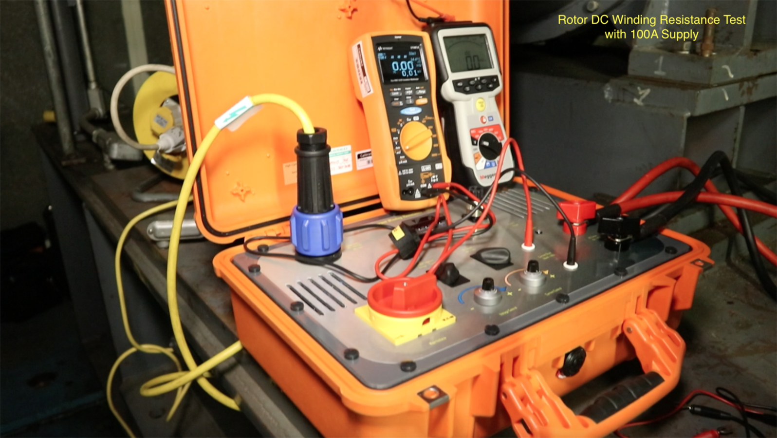
Rotor Winding DC Resistance


I do have a micro ohmmeter available to me to test winding resistance at 10A. The instrument however is not the best and will cut-out due to the time taken to allow the reading to stabilise due to the inductive nature to the winding. As an alternative, I have constructed a 100A variable DC supply and utilise a 4 wire methodology to measure the winding resistance at 5 different current values and then take an average as per the IEEE118 standard. The supply contains a 100A to 50mV current shunt that I connect a mV meter to, I then utilise the  MIT420/2MIT420/2 as a DC voltmeter connected directly across the rotor winding


imageimage


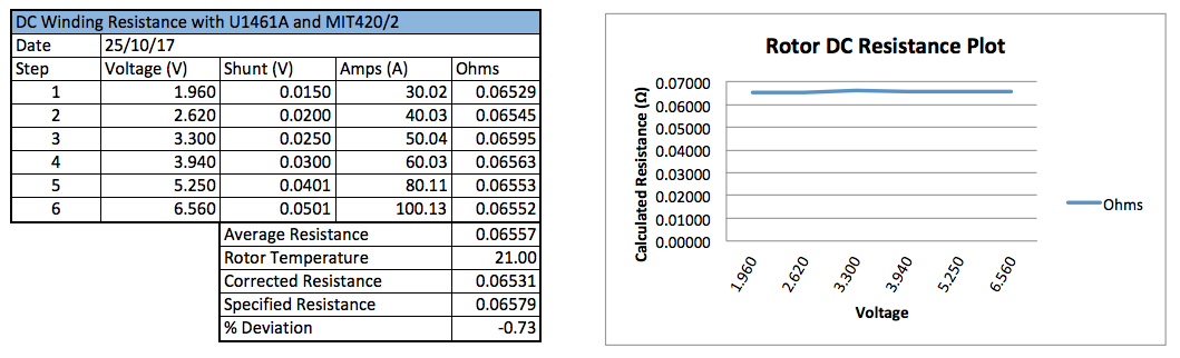
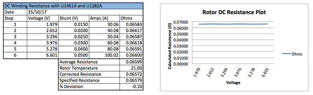
Both rotors tested reasonably well. For comparison on the 92MVA rotor, I repeated the test with the standard multimeter usually used in place of the  MIT420/2MIT420/2.


The  MIT420/2MIT420/2 produced a test result to -0.73% of the nominal DC winding resistance corrected to the specified temperature where as the usual test setup produced a result to -0.10% The specification is to be within 2 of the corrected value and so whilst the  MIT420/2MIT420/2 was not quite as accurate as the usual setup it still returned a result within tolerance


imageimage


Recurrent Surge Oscillograph Test (RSO)


The RSO test is a specialist test on a generator rotor winding to detect inter-turn faults within the winding. It works on time domain reflectometry. Pulses are injected alternately from the two ends of the windings and the reflected waveforms across impedances connected to the windings are compared. If the two traces overlap, then no fault is present. A fault is seen as a deviation in one of the waveform traces.


image


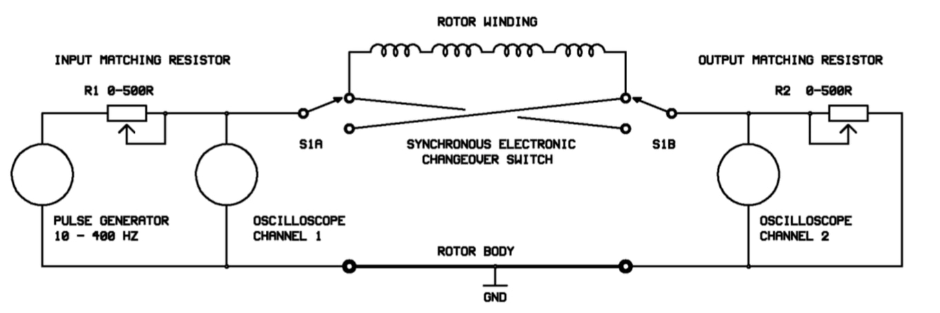
Details of rotor reflectometers and the test can be obtained from Rowdtest Ltd who manufacturer the units and provide the diagram above of the principle of operation.


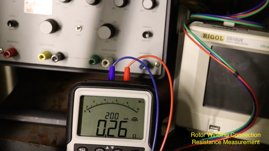
For this test I utilised the  MIT420/2MIT420/2 to measure the resistance of the test connections to the winding and to earth For an ideal RSO test there should be a maximum connection resistance of 1 Ohm across the winding and to earth This would usually be measured using the ohms function of a standard multimeter but I was curious to see if the automatic function of the resistance range on the  MIT420/2MIT420/2 would operate correctly across the inductive load of a large rotor winding As seen in the photo below the instrument function perfectly well recording a 0.26 Ohm resistance reading through the winding whilst sourcing a 200mA current.


image


Rotor Winding AC Impedance Test


The final test on the rotor winding is an AC Impedance test. This is an alternative test methodology to the RSO test for detecting inter-turn insulation faults. Where as the RSO test only applies 12V, in an AC impedance test, a voltage of up to 110V AC is applied across the winding, therefore applying more voltage across the inter-turn insulation. The test is carried out in the same manner as the DC winding resistance test, with the voltage across the winding and the current through it are measured at 10V steps and then the impedance calculated afterwards.


You don't have permission to edit metadata of this video.
Edit media
x
image
Upload Preview
image


A good rotor winding will produce a plot of impedance against voltage with a slight upward trend. An inter-turn fault in a winding is seen as a step change down in the impedance along the plot. There is also the opportunity to carry out a long term historical impedance trend of the winding at a specific voltage, nominated as 50V during my tests.


image


image


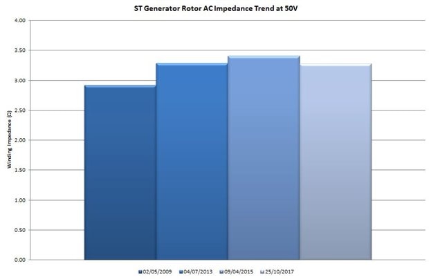
As can be seen from the plots above for the 92MVA generator comparable test results were achieved using the  MIT420/2MIT420/2 in place of a standard multimeter. Again the instrument has proved that it can be utilised in place of a regular voltmeter for the kind of tests that I carry out increasing its value and flexibility.

  • Sign in to reply

Top Comments

  • DAB
    DAB over 7 years ago +3
    Very good road test update. Thanks for a look at the motor winding industry. DAB
  • three-phase
    three-phase over 7 years ago in reply to DAB +1
    Many thanks DAB. The blog got posted before it was finished so I have now updated it added most of the details apart from the AC Impedance Video which continually refuses to upload the full length.
  • three-phase
    three-phase over 7 years ago +1
    Hurrah managed to upload the full video of the impedance test now
  • three-phase
    three-phase over 5 years ago in reply to engrkhan

    Hello,


    There are two options to carry out an impedance test on a rotor. Either as a step test demonstrated in this blog or as a pole balance test.


    With either method you will inject an AC voltage across the rotor connections and measure the current. For an IEEE compliant test, you can limit the current to 4A.


    For a step test, you only need access to the main rotor connections at the slip rings / diode pack. Measure the voltage and current at various steps until the current / voltage limit is reached and then plot the impedance values.


    If the rotor is removed / partially dismantled, you can carry out a pole balance test at one specific voltage. For a two pole rotor, the voltage is measured at the pole to pole lead to each rotor connection. If you are injecting 100V AC, then the voltages will be 50V from the pole to pole lead to either end for a balanced rotor. If the voltages are not matched there there is a potential fault that needs further investigation.


    If the test is for condition monitoring, then document the test set-up, equipment and measuring points so that the test can be repeated in the same manner for future comparison and trend building. If this is to find a potential fault then documenting the test set-up isn't so important.


    The test equipment can either be manually constructed as per this blog, consisting of a variac, ammeter and voltmeter or you can purchase test apparatus designed to do the measurements and record the results.


    Remember this is a live test injecting reasonable voltage levels that could give rise to danger, so appropriate safety measures need to be taken with the test set-up and whilst making the measurements.


    Kind regards.

    • Cancel
    • Vote Up 0 Vote Down
    • Sign in to reply
    • More
    • Cancel
  • engrkhan
    engrkhan over 5 years ago

    a very helpfull information provided on AC impedance test of rotor

    i am going to test a single rotor pole (AC impudence test ) kindly give me some suggestion how can i can i do rated voltage is 170 V (DC)

    • Cancel
    • Vote Up +1 Vote Down
    • Sign in to reply
    • More
    • Cancel
  • amankalra
    amankalra over 5 years ago in reply to three-phase

    Donald Lane  Really Thank You!     According to me, let me know about this, I am very grateful to you for the knowledge you gave me.

    If you ever come to India, please join me.

    Element14.Com This website is also a platform, we are able to stay away from each other and advise each other.

    Element14.Com is very grateful to you. Relaxed️

    Thank you so much All Community


    Regards.

    • Cancel
    • Vote Up 0 Vote Down
    • Sign in to reply
    • More
    • Cancel
  • three-phase
    three-phase over 5 years ago in reply to amankalra

    Yes, that is the shunt that I use. I just house it in a case from Hammond and install some 4mm binding posts to make the connections. This is the insides of the shunt. I mounted the shunt on a small piece of overboard suit would fit into the internal slots of the case.


    image


    I only use a current shunt because the current injected exceeds 10A that my multimeter can handle. You can overcome that by limiting the test current to less than 10A. Alternatively you can measure the current using a clamp meter, but I do not find this as accurate.


    It depends on what you want to achieve by your impedance test. Hydro Generator rotors are normally multipole, so the test is made by measuring the voltage drop across each pole and the values compared to make sure the poles are balanced.


    If this is just a routine test, then the set-up will be basic and the access into the rotor winding minimised. If this is searching for a specific fault in a pole, the the test would be more intrusive. You can also carry out DC winding resistance measurements or RSO tests as alternatives or supplements to an AC Impedance Test.


    Generally, unless you have your own technical support staff, such tests are carried out by a generator specialist contractor as part of their scope of works.

    • Cancel
    • Vote Up +1 Vote Down
    • Sign in to reply
    • More
    • Cancel
  • amankalra
    amankalra over 5 years ago in reply to three-phase

    Not available on the RS website. Not available with Hobut the current shunt. I need this product, where can I get it Besides multimeter, can I check with AC Milivolts meter. According to the shunt Given By you, It is found on the website.


    imageimage


    750 KW 3300 Volts Hydro Generator Also impedance Checks in any way ?


    Thank you so much your support.

    • Cancel
    • Vote Up +1 Vote Down
    • Sign in to reply
    • More
    • Cancel
>
element14 Community

element14 is the first online community specifically for engineers. Connect with your peers and get expert answers to your questions.

  • Members
  • Learn
  • Technologies
  • Challenges & Projects
  • Products
  • Store
  • About Us
  • Feedback & Support
  • FAQs
  • Terms of Use
  • Privacy Policy
  • Legal and Copyright Notices
  • Sitemap
  • Cookies

An Avnet Company © 2025 Premier Farnell Limited. All Rights Reserved.

Premier Farnell Ltd, registered in England and Wales (no 00876412), registered office: Farnell House, Forge Lane, Leeds LS12 2NE.

ICP 备案号 10220084.

Follow element14

  • X
  • Facebook
  • linkedin
  • YouTube