


Noise Measurements Using R&S RTM3K Oscilloscope
This blog is in continuation from the Rohde & Schwarz Oscilloscope Kit RTM3K-COM4 - Review
Noise plays an important role in measurements and it can be internal or external. Typically the noise floor of an oscilloscope is in the range of millivolts peak-to-peak. Some of the ways to reduce noise in the circuit is by setting a BW limit filter of 20 MHz or using the average acquisition mode. In the averaging mode the noise gets canceled out.
Noise parameters of interest are:
- Crest factor: Ratio of the peak value to the RMS value of the waveform
- AC RMS Noise of the scope
- Measuring the Vpeak-peak of the Noise Signal

Setup for NULL Noise Measurements
- Short all the input channels using 0 ohm short circuit cap to prevent any external signal coupling at the BNC inputs

- Set to maximum record length 80MSa
- Set the sensitivity to highest 500uV/div and horizontal to 500 ps/div
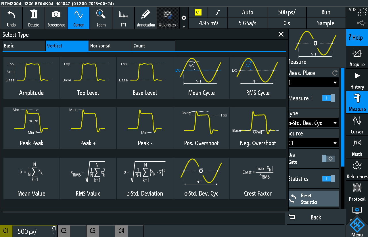

Fig: Measurement options
- Measure 1 channel at a time to get the maximum sampling rate of 5Gs/sec.
- Repeat for all channels and different Bandwidth as the noise floor decreases with BW.
- Set the scope display to infinite persistence to check how thick is the resulting waveform.
- 1:1 probe settings must be used and not the standard 10:1 settings

Fig: Setup Settings
Measuring the oscilloscope noise floor
Results of the measurements:
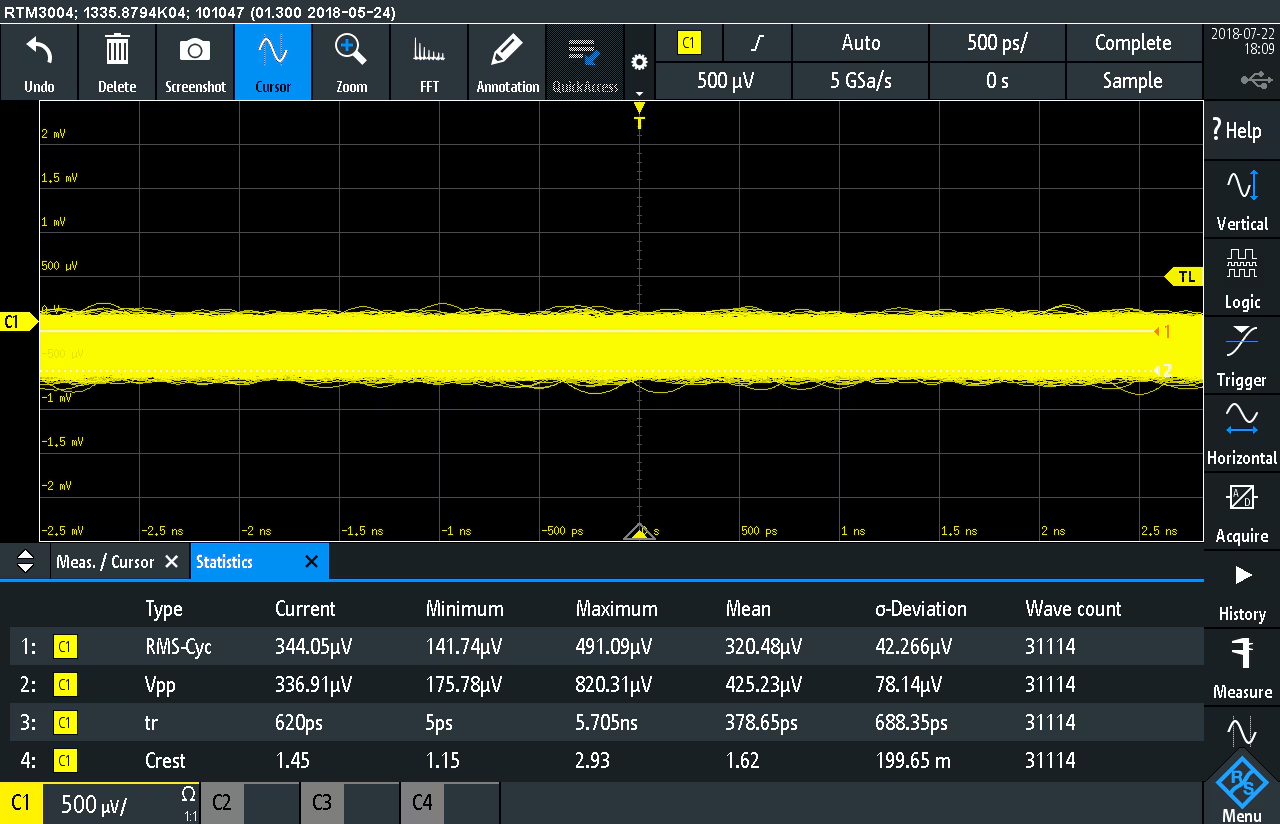
Fig: Channel 1 with Full Bandwidth 1GHz. 500uV/div and 500ps/div sensitivity
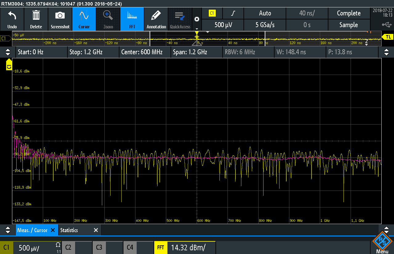
Fig: FFT Channel1 with Full Bandwidth 1GHz. 500uV/div and 500ps/div sensitivity

Fig: Channel 1 with BW Limit 500MHz. 500uV/div and 500ps/div sensitivity

Fig: FFT Channel1 with Full Bandwidth 500MHz. 500uV/div and 500ps/div sensitivity
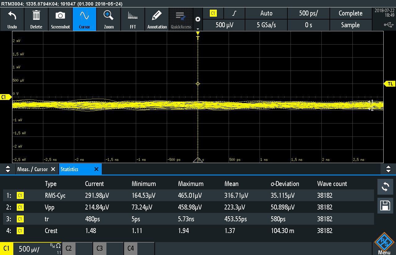
Fig: Channel 1 with BW Limit 350MHz. 500uV/div and 500ps/div sensitivity
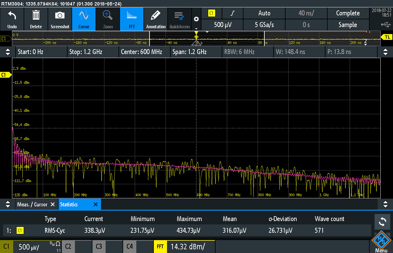
Fig: FFT Channel1 with Full Bandwidth 350MHz. 500uV/div and 500ps/div sensitivity
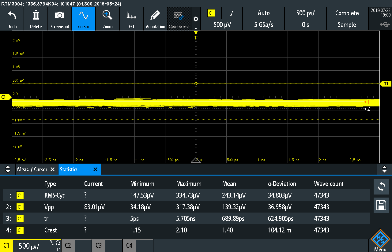
Fig: Channel 1 with BW Limit 200MHz. 500uV/div and 500ps/div sensitivity
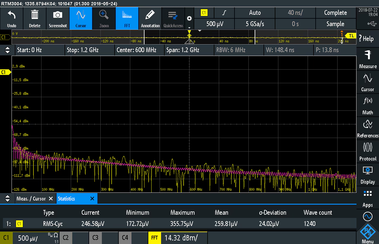
Fig: FFT Channel1 with Full Bandwidth 200MHz. 500uV/div and 500ps/div sensitivity
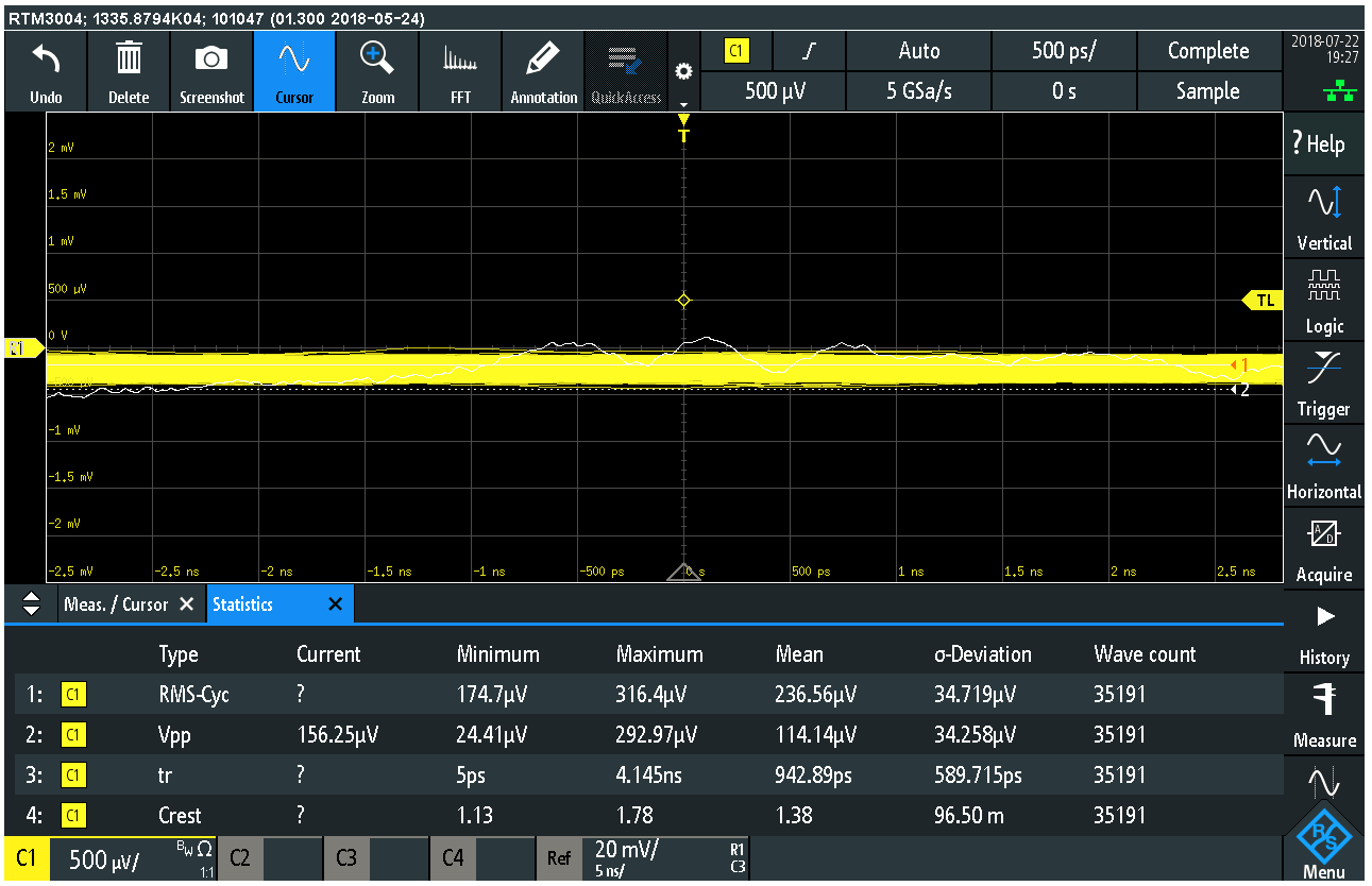
Fig: Channel 1 with BW Limit 100MHz. 500uV/div and 500ps/div sensitivity
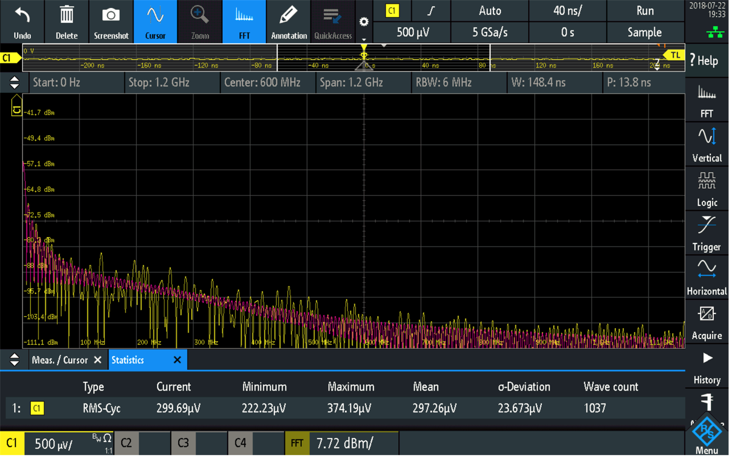
Fig: FFT Channel1 with Full Bandwidth 100MHz. 500uV/div and 500ps/div sensitivity
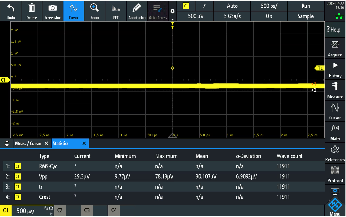
Fig: Channel 1 with BW Limit 20MHz. 500uV/div and 500ps/div sensitivity
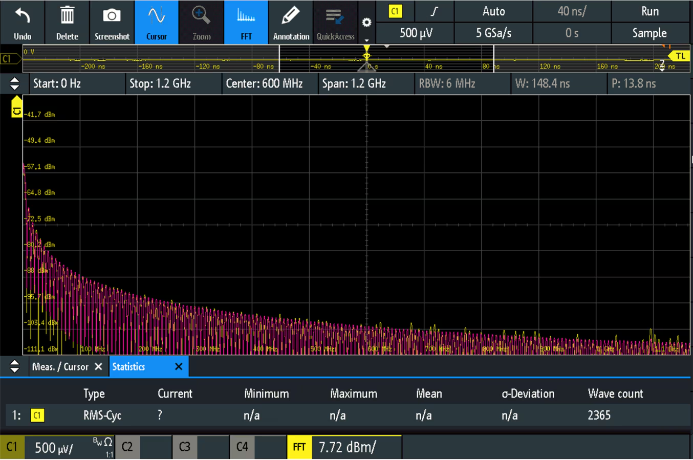
Fig: FFT Channel1 with Full Bandwidth 20MHz. 500uV/div and 500ps/div sensitivity
Channel 1 500uV/div and 500ps/div sensitivity at 5 GSa/s
| Bandwidth Settings | Crest factor | AC RMS Noise uV | Vp-p Noise uV | FFT dBm |
|---|---|---|---|---|
| 1GHz | 1.62 | 320.48 uV | 425 uV | -62 dBm |
| 500 MHz | 1.41 | 313 uV | 267 uV | -62 dBm |
| 350MHz | 1.37 | 316 uV | 223 uV | -54.4 dBm |
| 200MHz | 1.4 | 243 uV | 139 uV | -54.4 dBm |
| 100MHz | 1.38 | 236 uV | 114 uV | -57.1 dBm |
| 20MHz | ------ | ----- | 30.17uV | -57.01 dBm |
Channel 2 500uV/div and 500ps/div sensitivity at 2.5 GSa/s
| Bandwidth Settings | Crest Factor | AC RMS Noise uV | Vp-p Noise uV |
|---|---|---|---|
| 1GHz | 2.25 | 121.42uV | 395.65 |
| 500MHz | 2.04 | 110.25uV | 268.84uV |
| 350MHz | 1.99 | 99.195uV | 215.17uV |
| 200MHz | 2.00 | 68.13uV | 135.76uV |
| 100MHz | 1.85 | ------- | 111.92uV |
| 20MHz | ------- | ------- | 28.242uV |
Channel 3 500uV/div and 500ps/div sensitivity at 5 GSa/s at 1 GHz Full BW
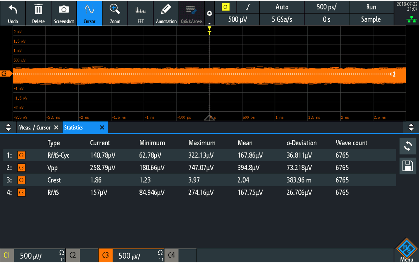
Fig: Channel 3 with Full Bandwidth 1GHz. 500uV/div and 500ps/div sensitivity
Channel 4 500uV/div and 500ps/div sensitivity at 5 GSa/s at 1 GHz Full BW
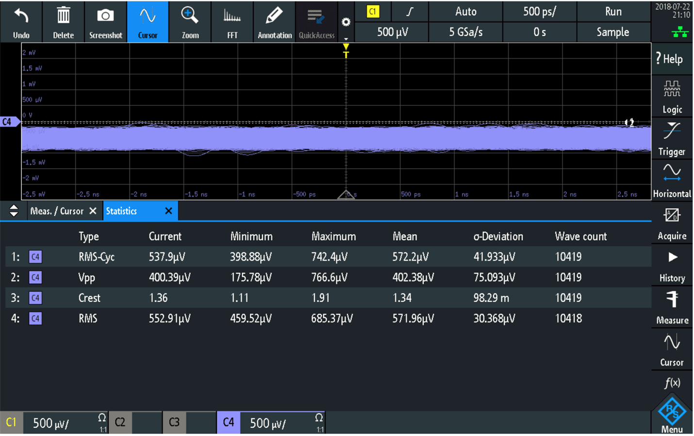
Fig: Channel 4 with Full Bandwidth 1GHz. 500uV/div and 500ps/div sensitivity
Noise at Multiple Channels ON at 1GHz Full BW

Fig: Full BW Measurements all 4 channels
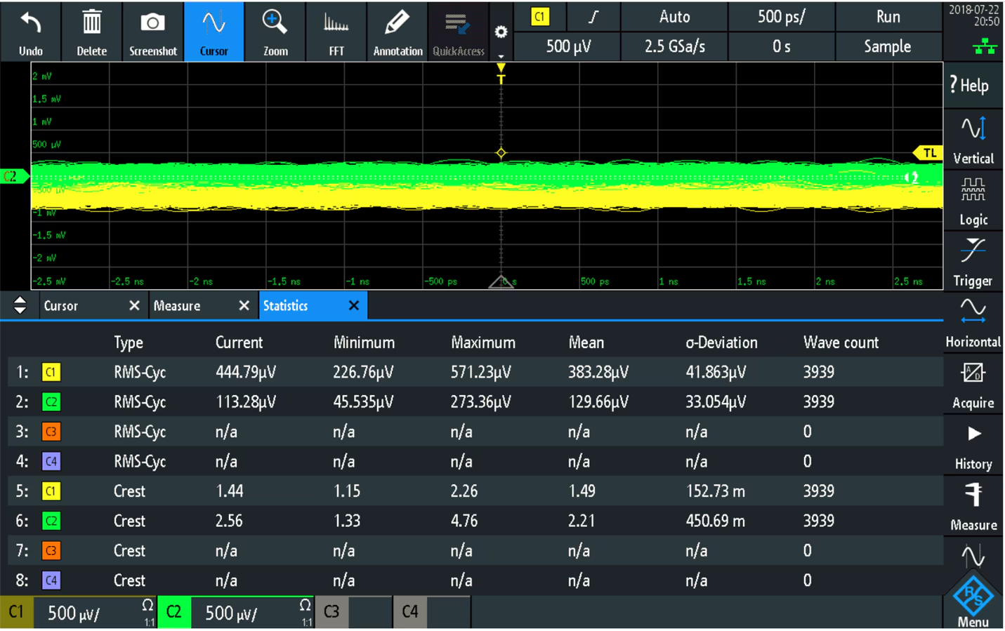
Fig: Full BW Measurements for Channel 1 and Channel 2
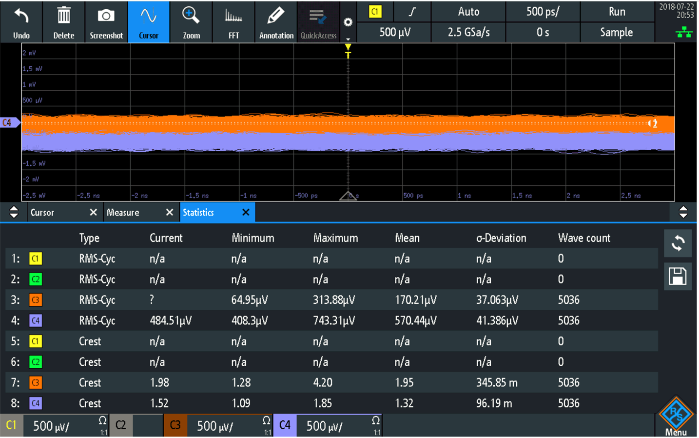
Fig: Full BW Measurement Channel 2 and Channel 3
From the analysis; one can conclude that each analog input has its own different internal noise levels which also depends on the channel used and the number of ON channels at a time. The internal noise degrades as all the channels are turned on and is at full bandwidth with highest sampling rate.
Here one can see that the internal noise floor of the oscilloscope is a function of multiple parameters (specially the Bandwidth settings and even the channels) which must be considered during before signal measurements. The R&S RTM-3004 stands upto its specifications and delivers a very low internal noise. In some oscilloscopes of low range one can check that the noise floor varies significantly as all the channels are turned on but the RTM 3004 delivers similar noise floor irrespective of the number of channels used.
RTM- 3004 Oscilloscope Noise as a function of Sensitivity
The baseline noise of RTM 3004 1 GHz oscilloscope at different vertical sensitivities (volts/division)
| Vertical Sensitivity (Volts/div) | RMA Noise Floor at the 50 ohm BNC |
|---|---|
| 1mV/div | 345uV |
| 2mV/div | 343uV |
| 5mV/div | 499uV |
| 10mV/div | 552uV |
| 20mV/div | 955uV |
| 50mV/div | 2.4mV |
| 100mV/div | 4.4mV |
| 200mV/div | 8.78mV |
| 500mV/div | 18.462mV |
| 1V/div | 29mV |
Such techniques must be kept in mind when measuring small signals or signals where measurement system noise plays an important role.
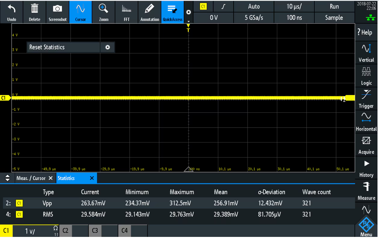
Fig: Noise vs Sensitivity
Noise Comparison with Keysight Tektronix and LeCroy 1GHz Bandwidth MSOs
RMS and peak-to-peak noise comparisons of 1-GHz bandwidth MSOs

Fig: RMS noise comparisons
 Fig: Typical Peak to Peak Noise
Standard Noise Generator Noisecom NC6110
The Noise generator NC6110 generates a steady noise signal output which has a cutoff frequency at 1.5 GHz. The test setup here was meant to measure this noise signal roll off but it turns out that this signal needs a higher bandwidth scope hence I was able to only measure the FFT of the noise output with the RTM 3004 which was in the 1GHz bandwidth range.
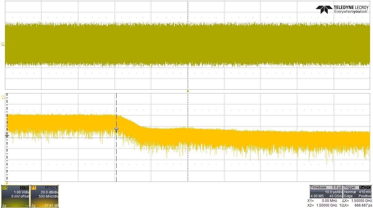
Fig: 1.5GHz Noise signal as measured by 8GHz LeCroy
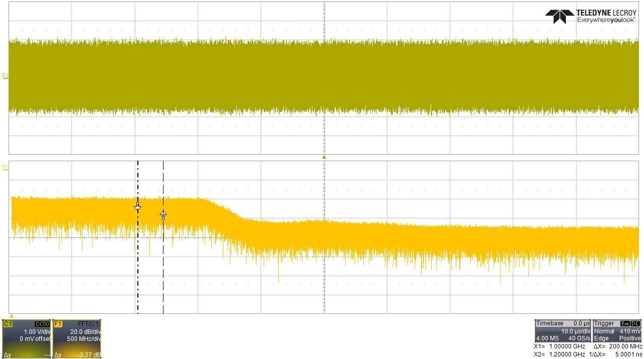
Fig: 1GHz to 1.2 GHz Noise signal as measured by 8GHz LeCroy
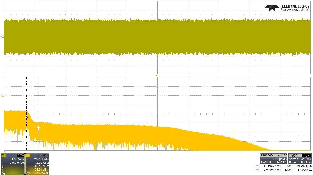
Fig: 1.5GHz Noise signal -3dB roll off as measured by 8GHz LeCroy
This measurement was done in the flat range across the whole bandwidth of the scope upto 1.1 GHz. The noise signal has a pretty flat rate FFT transform as is confirmed with the above LeCroy scope.
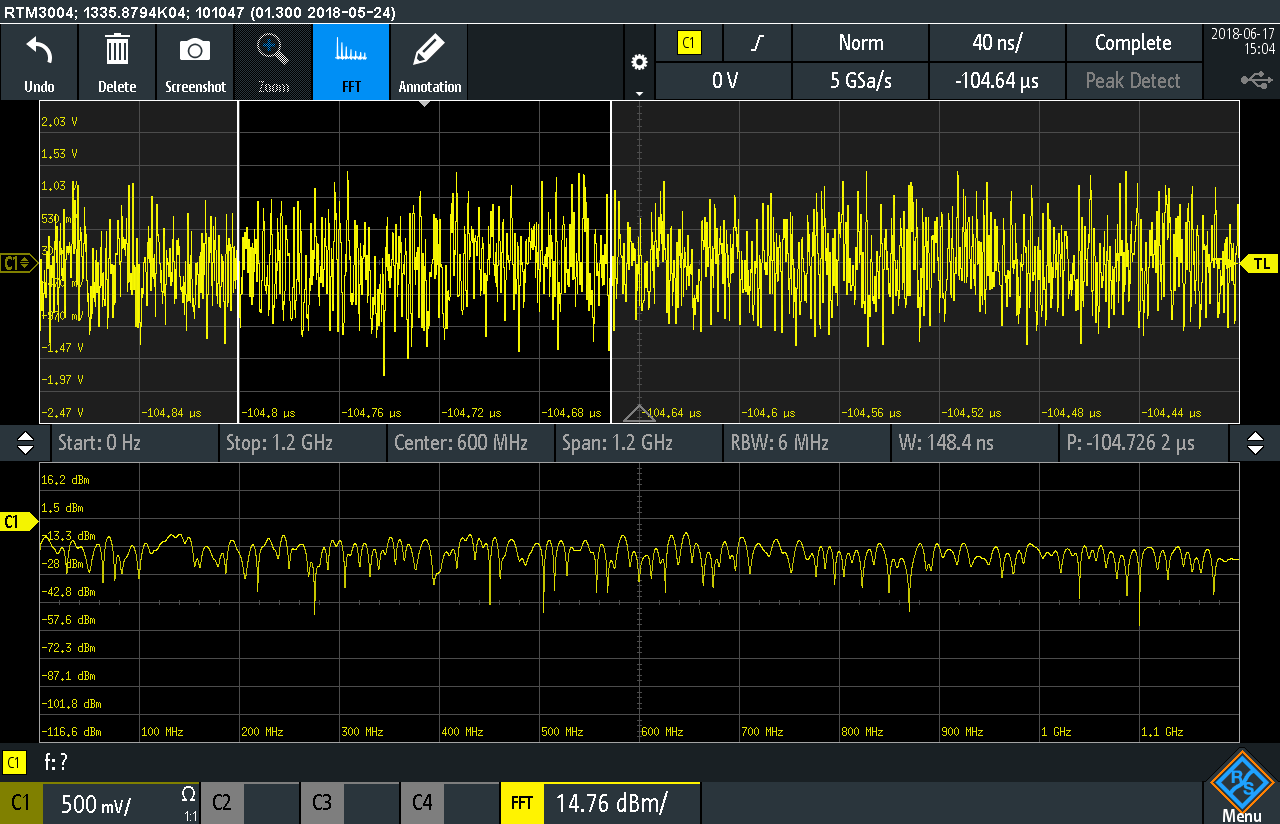
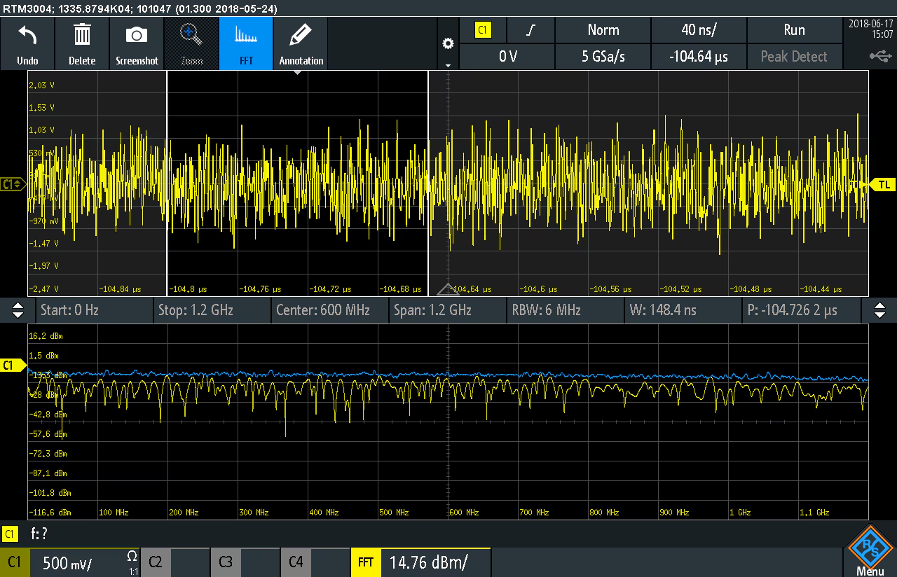
Fig: The FFT of the Noise signal as measured by RTM 3004 in the flat Range upto 1.1 GHz
In conclusion; noise has a significant impact on the horizontal and vertical measurements. The lower the internal oscilloscope noise is the better one can measure the smaller signals.
Please continue here to the main blog Rohde & Schwarz Oscilloscope Kit RTM3K-COM4 - Review
Top Comments