


Power measurements and testing Voltmeter DVM
This blog is in continuation from the Rohde & Schwarz Oscilloscope Kit RTM3K-COM4 - Review
Here I setup an experiment to measure the ripple and do power analysis of the DC/DC TPSM84A21 Power Module. It is an integrated power solution that combines the TPS54A21, a 10-A, DC/DC, synchronous, step-down converter with power MOSFETs, shielded inductors, input and output capacitors, and passives into a package. The tests were done with 10V and 12V input voltage and outputs in the range of 0.6V, 0.8V,1V, 1.1V, 1.2V were measured.
Datasheet TPSM84A21 Power Module
A detailed description of the TI SWIFT Power Module EVM can be seen here. I will focus on the measurements with the R&S RTM 3004 Oscilloscope.
Power measurements in the RTM 3004
Fig: How to Set up the RTM 3004 for Power Measurements
The R&S RTM K31 Power Analysis bundle offers different options to measure input and output of (Switched Mode Power Supplies) SMPS and DC/DC Converters. The TPSM84A21 Power Module is a high current DC/DC converter. The power analysis of the DC/DC converter is presented below.
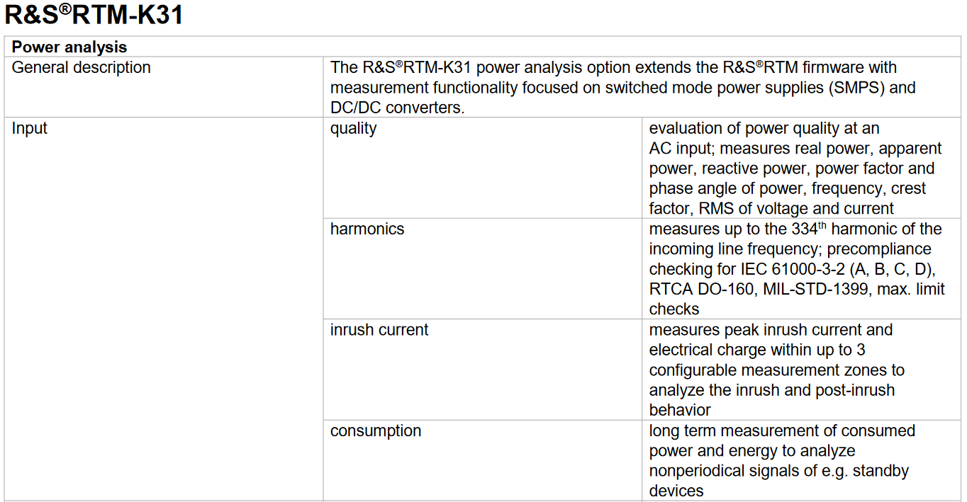
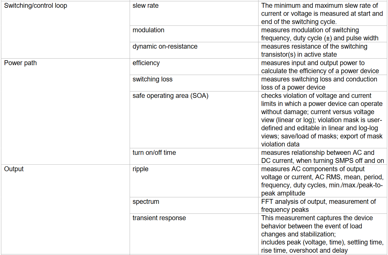
Fig: R&S RTM K31 Power Analysis bundle offers
Setup of the TPSM84A21 Power Module
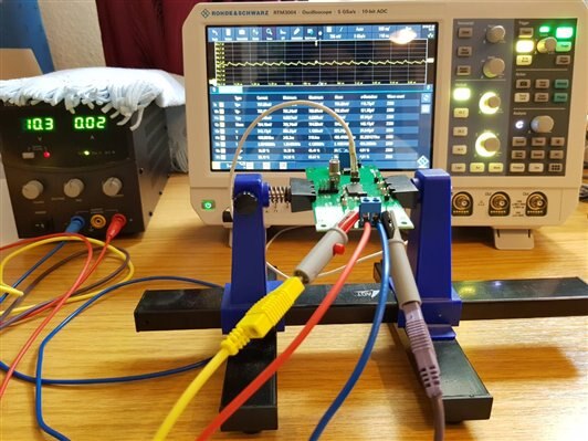
Fig: Test setup for the Power Measurements
Measurements with the TPSM84A21 Power Module
The below measurements were done using the automated power analysis tool in the RTM 3004 with the DC/DC TPSM84A21 Power Module.
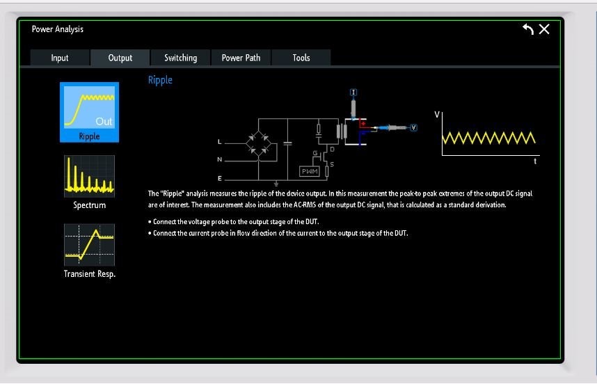
The aim is only to present how this automated button of power noise ripple works and the below mentioned tests were done with no load in the DC/DC converter output.

Fig: Power Analysis of the 0.6V output of the DC/DC TPSM84A21 Power Module
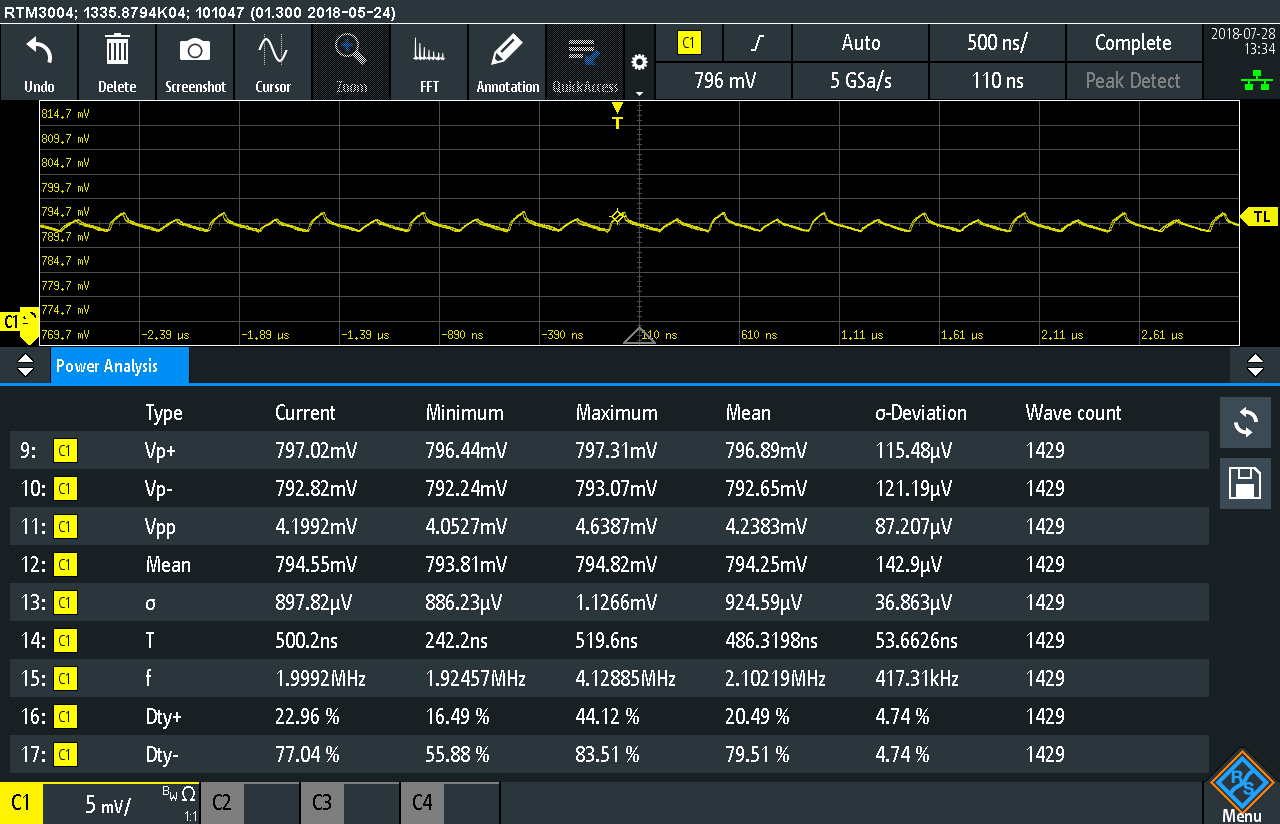
Fig: Power Analysis of the 0.8V output of the DC/DC TPSM84A21 Power Module

Fig: Power Analysis of the 1V output of the DC/DC TPSM84A21 Power Module
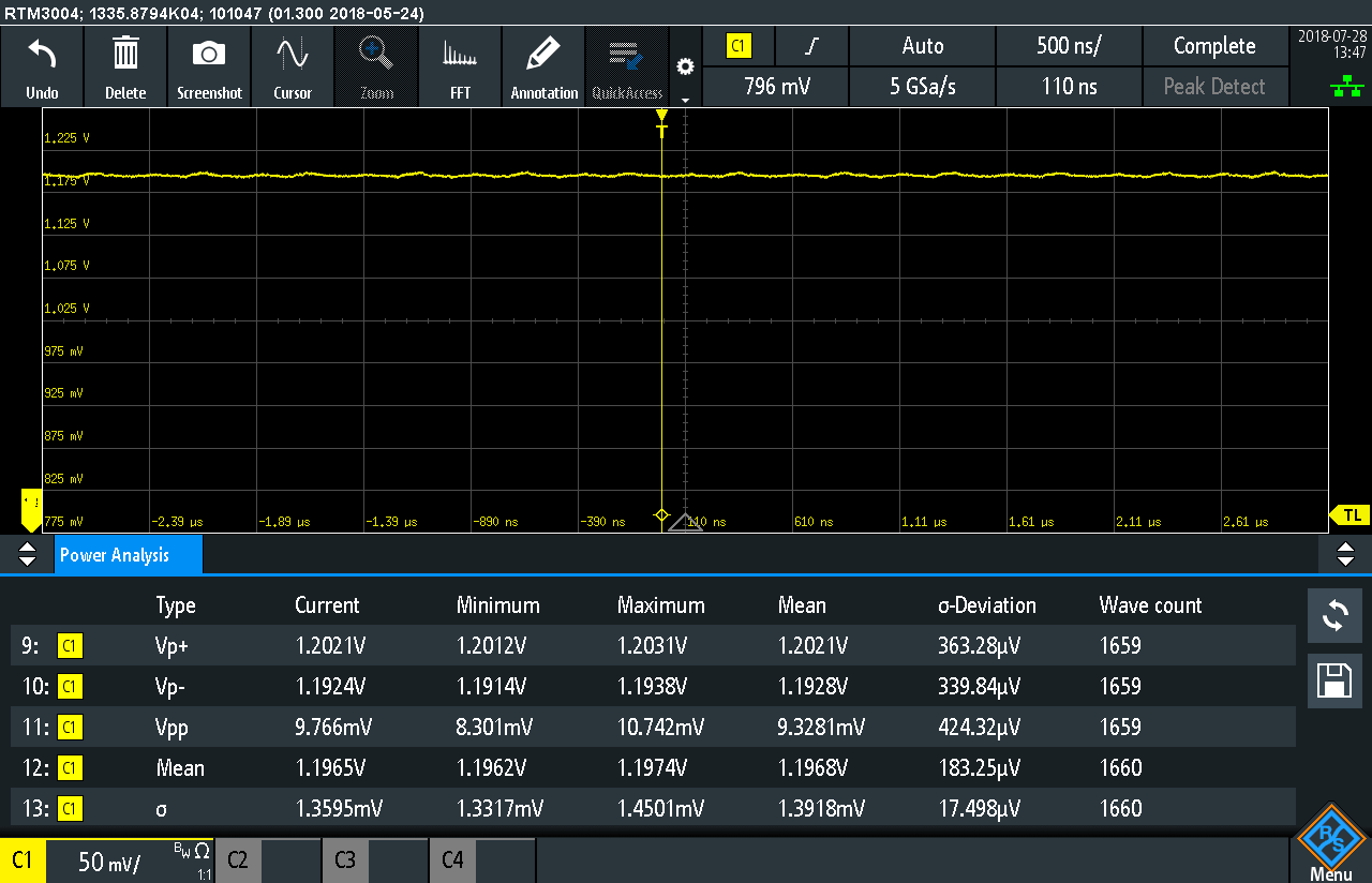
Fig: Power Analysis of the 1.2V output of the DC/DC Converter Module
Fig: Power Analysis of the DC/DC Converter
The tests here will be done with fixed resistance load in the DC/DC converter output.
tbd.. new addition of test on popular demand
Spectrum analysis of the Output voltage
The settings to measure are as below. The Vin = 12V and Vout = 0.8V of the DC/DC TPSM84A21 Power Module. The frequency measured of the output signal is as measured above is 2MHz
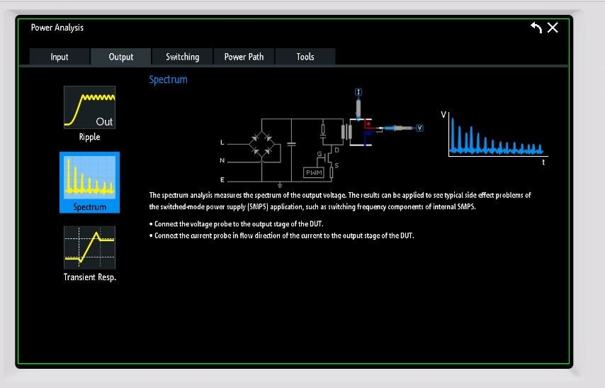
Fig: Settings for spectrum analysis
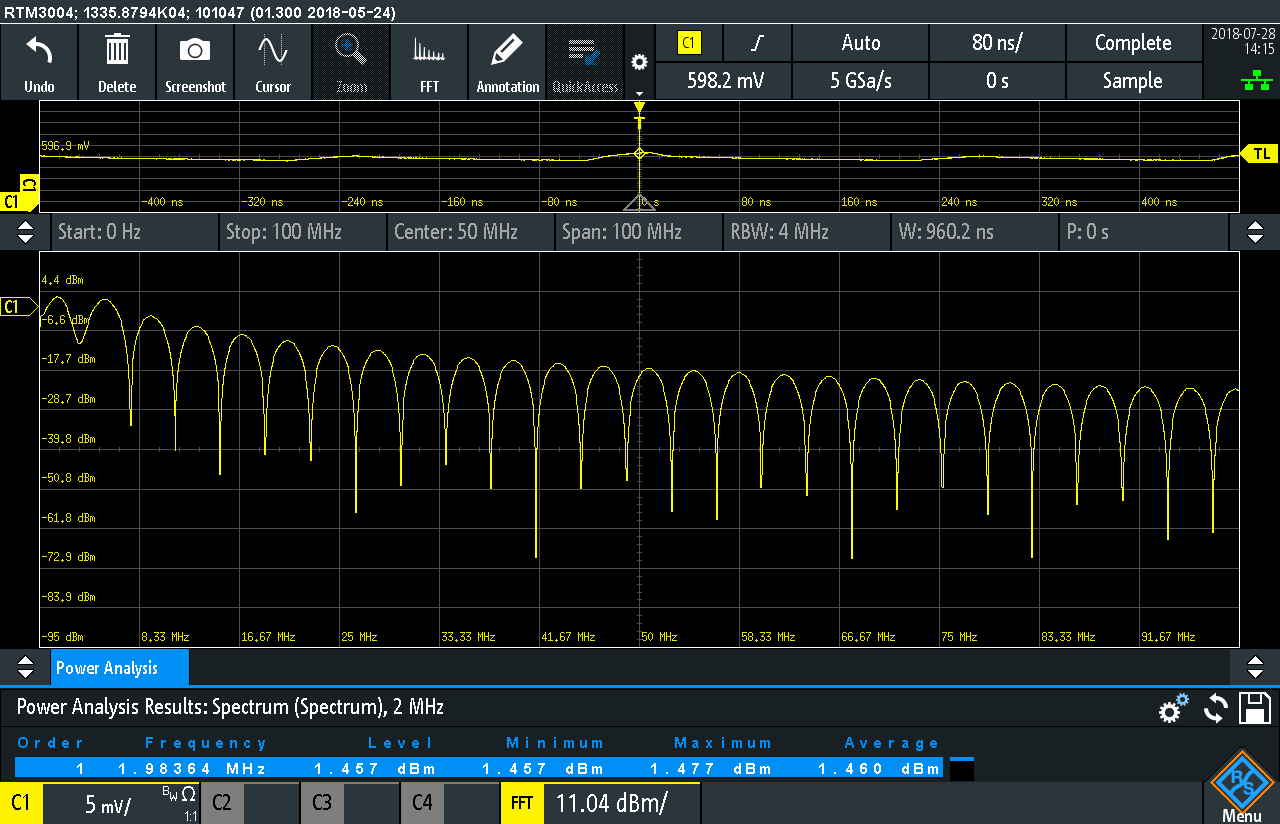
Fig: The spectrum output for Vout = 0.8V
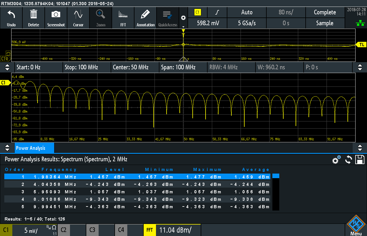
Fig: Detailed look into the measured data
The minimum horizontal measurement setting for RTM 3004 is 8MHz hence the spectrum behavior immediately after the switching of the device cannot be analyzed here as it is around 2MHz.
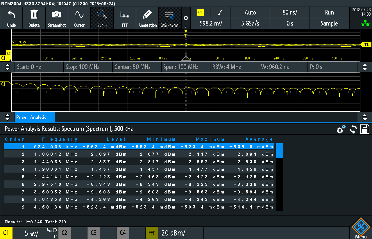
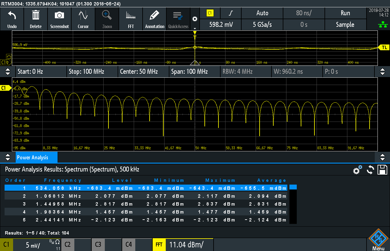
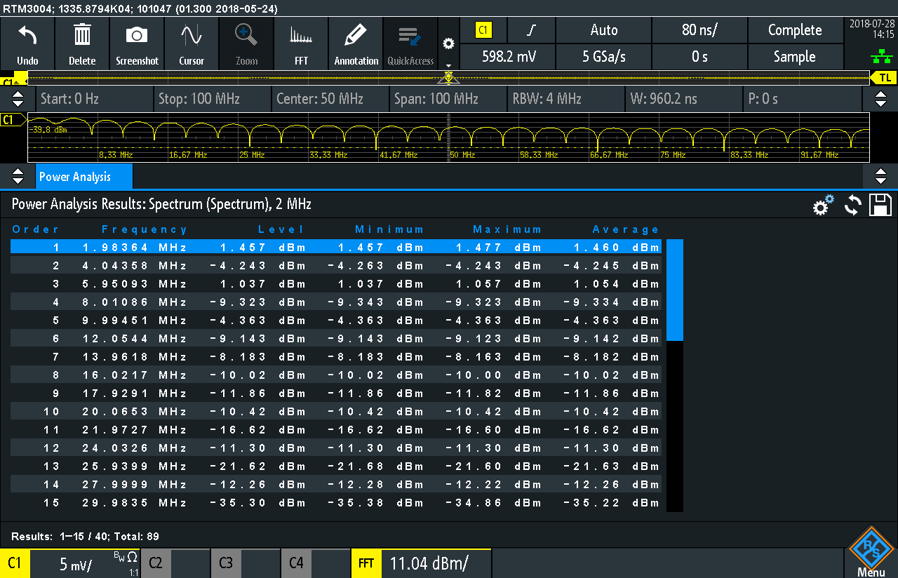
Fig: Detailed look into the measured data
Transient Analysis of the Output voltage
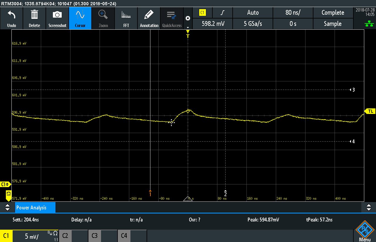
Fig: Measuring the transient response on the output signal for Vout = 0.6V
Measuring with Digital Voltmeter in RTM 3004
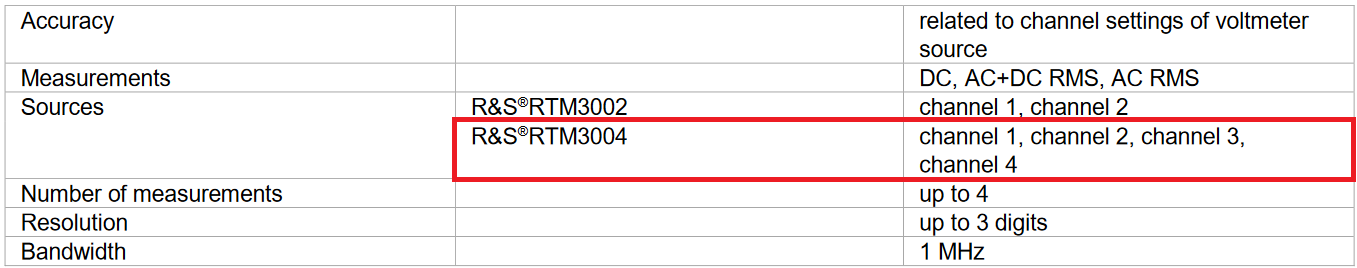
Fig: DVM features of RTM 3004
Below, the DVM can be seen live in action and measuring the input signal voltage of the DC/DC TPSM84A21 Power Module.
Fig: Measuring with the DVM in RTM 3004
In conclusion the power measurement features of the RTM 3004 are quite powerful & allows results to be obtained with minimum effort. By one click of the button the scope settings are done and one can do fast measurements instead of investing time for finding the correct settings for the tests.
Top Comments