MXO4 Road Test and an Audio Amplifier
A recent thread on E14 discussed a simple valve pre-amplifier.
/technologies/experts/f/forum/52476/i-have-a-small-audio-amplifier-project-i-am-working-on
The thread starter, /members/rcayot, had some issues about power the amplifier. I had a look on the web and found the schematic below:

Kits for this amplifier are available from many different sources, using parts of differing quality. Obviously thousands of these kits have been sold. There are multiple Yout tube videos and a few test reports. Not least one from E14 member Gough Lui. https://goughlui.com/2019/03/24/project-diy-more-tube-based-pre-amp-kit-6j1-fever-clone/
Despite a good look on the web I couldn’t find any references to the original designer of this amplifier.
I’m not in any way an expert on thermionic valves (tubes), but I was puzzled about the popularity of this design – at first glance it looks to be a truly awful design – how could it possibly provide a decent performance ?
I said in my proposal for the MXO4 that I would do some audio testing – this looks like good chance - so I bought a kit from Amazon (not the cheapest source but it came the next day.
My kit uses some fairly grim components (1uF ceramic caps in the signal path) but at least it had 50V capacitors for the nominal 30V supply. (Gough’s kit came with 35V caps which is pretty cheap-skate but he got film capacitors.)
My kit had no instructions or schematic but the board was marked with component IDs and values – so it went together OK.
I mis-remembered having a small 12V transformer but I couldn’t find it. A while ago I bought some 2 x 12V transformers from Farnell on a clearance offer, £4 each for a 200VA transformer was irrestible so I bought the 8 that they had. So far I’ve used one in dual power supply – so there were plenty left.
It’s a bit over the top for a pre-amp.
Poly Doh to the rescue again.
Time that Poly was established as a fully fledged super-hero ! Those lethal mains terminals need some protection. Here’s the Poly Doh as it sets.
I started the board up with 150R 1W resistor in series with the supply and powered the mains transformer via a Variac.
Apart from a minor issue ( I forgot that the input attenuator control has a power switch built in) the power came up OK.
This is the test set up.
I took the picture with the wrong output connected !
Testing the Amplifier
First off, I just played about with it a bit. I used the MXO4 built in signal generator, connected to the amplifier via a BNC to Phone adapter, an in-line BNC 50R terminator and then a BNC co-axial cable to the scope Gen 1 output. It’s a set up that should be good for at least 50MHz so should be OK !
I used a Neutrik AI Audio Test Set to measure distortion and the scope to measure signal levels.
The MXO4 was supplying the test signal so I checked it directly connected to the Neutrik A1.
That's a good low distortion for a scope based sign gen.
The amplifier seemed to work on both channels (I won’t quite go so far as to say it worked well or even OK, as we shall see.)
It was noisy and very susceptible to picking up RF, at first I thought it was oscillating but it turned out to be radio signals. Standing the amplifier on the grounded metal plate and keeping fingers away during measurements fixed this. You really do not need or want an audio amp to have 1MHz bandwidth.
The amplifier design is odd ! It biases the valve grids with about 30V, the cathode resistor is so low a value that there is no significant voltage across it at the operating current. So the operating current is set almost entirely by the anode resistor and the valve characteristics. With carefully matched and selected valves this might be OK but these valves are anything but carefully selected.
On my amplifier the anode currents of the two channels (determined by measuring the voltage drop across the 4k7 anode resistors R15 and R20) were 1.93 and 1.10 mA.

Channel 1 had a gain of 7.06 = 17dB (at output level = 125.65 mV RMS)
Increasing the signal level results in increasingly distorted output, I didn’t bother going all the way to clipping, at 4V RMS the distortion is about 8% and clearly visible on the scope.
The distortion (THD + noise 40kHz bandwidth) was about 1% at 1V RMS (measured on Neutrik A1).
The mains hum is awful. (Many comments and possible fixes on the web.) The wideband S/N ratio is 56dB, with the 400Hz filter in it goes up to 83dB. (Neutrik again.)
Channel 2 is the one with the low anode current, gain is 6.028 = 15.6dB. The THD was predictable worse, 7% at 2VRMS out, 3.2% at 1V and 1% at 0.29V.
So far I’ve established the basic performance of the board using the scope as a signal generator or DMM and a very classical (not mention old and obsolete) audio test instrument.
The MXO4 talks a lot in the promotional literature about the goodness of it Spectrum Analysis capabilities. So, let’s take a look at the noise, distortion etc all at once with the spectrum analyser.
Spectrum Analyser Measuring Noise and Distortion
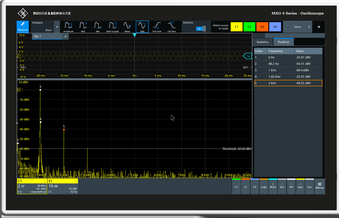
After a lot of fiddling this was the best I could do to show the noise and distortion on the MXO4.

This 10kHz bandwidth view gives a reasonable idea of the distortion The noise floor is very low but the 50Hz hum, although picked up by the peak detector is not visible on the screen. The automatic peak detection has picked up a spur on the 1kHz fundamental and shows the 1% or so 2nd harmonic level with marker 5. I couldn't set the peak detect to pick up th second harmonic but avoid the spur.
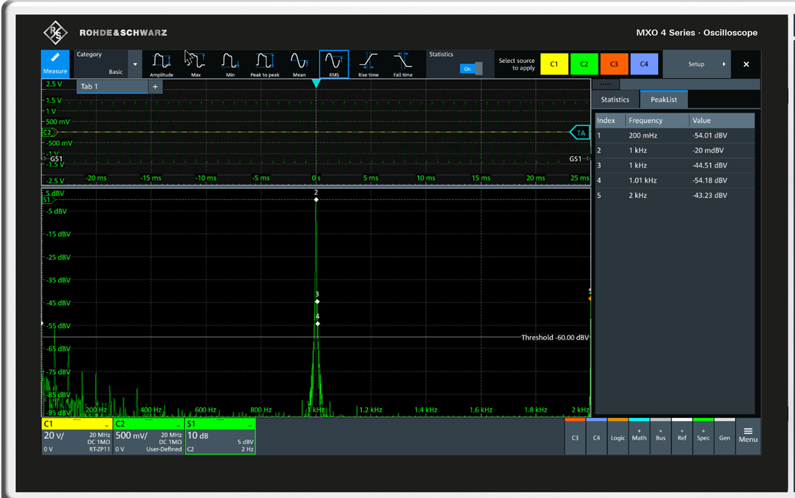
By reducing the bandwidth we can see the LF stuff at the left of the screen.

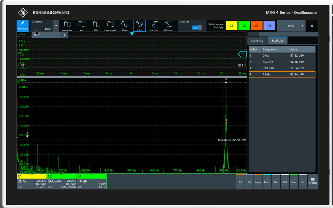
To keep the level reference, we need to be able to capture the 1kHz signal, this is going as low bandwidth as we can:

By selecting a different tab in the results we can measure the gain at the same time. There doesn't seem to be a way to show both tabs at once.
This does seem like a lot of faffing about to look at the audio spectrum – by now you’ll be wondering why on earth I didn’t select a log frequency scale – the normal way of looking at wideband Audio Frequency spectra, And the answer is that the R&S spectrum analyser doesn’t support it.
Is it a ridiculous ask ?
The Keysight DSO-X 3024T and Rigol HDO4204 don’t support log frequency axes either. But the Picoscopes do (all of them - a sub £500 Picsocpe will plot log axis spectra).
This was what a more up-market Picoscope makes of the problem:

SINAD is Signal-to-noise and distortion ratio, see WIKI
https://en.wikipedia.org/wiki/SINAD
The Pico can’t show normal channels at the same time as spectra, but in exchange it can show everything from 20Hz to 100kHz at once, and calculate SINAD and THD as well. It doesn’t do the peak detect thing (which is good for RF but not much help here), but it does have easily positioned cursors.
I can forgive the Keysight – its quite an old design and honestly refers to an FFT capability rather than a Spectrum Analyser. I can forgive the Rigol – it's less than 20% of the price of the R&S and pretty low noise as well.
But the MXO4 has all the hardware to be great - but with the current software it just isn’t.
Improving the Amplifier
I’ve mentioned the wide bandwidth of the amplifier.
I used the FRA capability of the R&S to take a look at it:

The FRA uses a log frequency scale (good here) but with no option of linear !
I’m not sure about that odd ripple at just below 100Hz - might check it later but I suspect the scope.
The gain matches our other measurements and the frequency response is about 3dB down at 1MHz. That’s far too wide for audio.
The amplifier has a 4.7kR poutput impedance (ie the anode resistance) to I have tamed its bandwidth with a 1nF film capacitor across each of R15 and R20.
That gives this response:

I’ve used the markers to show that it’s now down 3dB at 44kHz which is a lot more sensible.
It’s a pity that the phase unwrapping can’t plot the phase through zero transition better but in this case the FRA is doing the job.
No idea why the 1nF cap has also killed the ripple just below 100Hz, perhaps the first plot was zapped by some RF at just the wrong moment.
Summary
In this blog I’ve been looking at two things, the valve pre-amp and the MXO4.
Valve Pre-Amp
Starting with the pre-amp – it’s possibly the worst pre-amp I have ever tested. As supplied the noise and distortion are terrible, the two channels don’t match and the bandwidth is far too wide. If you like the sound of full spectrum distortion and random radio with your music – then go for it. Otherwise, it’s value is as a cheap way to play with a valve circuit (which is quite fun).
MXO4 and Audio
The MXO4 core scope functions are great for audio, very low noise, and high resolution. (With oversampling very high resolution.)
The spectrum analysis feature gets a lot of exposure in R&S promotions, but it is missing some of the key features that you need for audio (or other low frequency) work.
It needs the additions of log frequency scale, more flexible marker positioning and automatic calculations of THD, SINAD, and noise.
The MXO4 has the hardware capability to replace most of the functions of classical Dynamic Analysers like the HP3580A, HP35660A, B&K 2131 as well as filter based audio measurement Analysers like the Neutrik A1 and HP8903B but the software just doesn’t match up to the hardware.
To end on a good note, despite the problems with the FRA function (discussed in an earlier blog) it was capable of checking the pre-amp and helping improve it.
And the MXO4 is nice to use as straight scope.
