This is the third and last blog post before the final review for the Rohm BD9G500EFJ-EVK-001 RoadTest. Here, I'm going to explore one of the many tools Rohm has available on its website to assist with the design process.
To get access, you have to create a Rohm account and then you can use them from the BD9G500EFJ-LA product page. I will focus mainly on the online simulation tool, but it's worth mentioning that they also provide a PSpice model (they used it with Orcad) with a very good application note that compares simulation and real measurement results.
Online simulation tools. Registration is required.
Frequency response simulation
Once registered, you get access to an already prepared test scheme, ready to simulate. There are some global parameters that make simulation set up even faster.
Frequency response simulation with 3A output current
Honestly, I didn't even check the simulation guide they provided because it wasn't necessary for me to get up and running with the web tool.
I played around with components value a little bit and reproduced on the simulator the design I tested in the second blog. Unsurprisingly, in the evaluation board they designed the feedback loop to be as good as possible without excessive overshoot and that carried over to my design as well.
One interesting thing that I noticed is that, by derating the C6 ceramic output capacitor inside the simulator, the phase margin gets marginally better.
Frequency response with C6 derated from 47uF to 30uF. Phase margin increased by a little bit (about 4°)
It's also interesting to observe that the crossover frequency is not at 60kHz (as I was aiming for) but it's about 45kHz. This is coherent with the data they reported in their documentation as well, achieving about 16kHz when setting a theoretical crossover frequency around 20kHz.
Transient response simulation
To edit the simulation circuit, you have to click on "Edit in PartQuest Explore" so I did that to simulate my circuit in the time domain.
After editing the circuit, my first simulation try was unsuccessfull due to a convergence problem.
The solution was quite easy: I enabled the time domain optimization and I reduced the timestep resolution inside the option menu.
Simulation parameters I used to get rid of the convergence problem
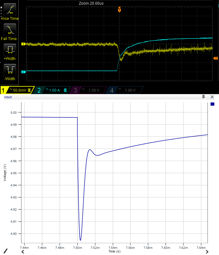
Transient simulation: 3.5A step load
We can notice an initial overshoot at the simulation beginning: that's just an artifact because the model probably doesn't include the soft start. To me, that's nothing to worry about.
So, how does the simulation compare to my measures?
Well, I have to say that it's pretty close!

My impression
My experience with the online simulation tool has been positive. Having the circuit ready to be simulated allowed me to start more easily with the simulation and results were accurate.
Scheme modification has been easy and, other than an easy fixed convergence problem, there were no big issues.
