


Resolving Errors | |
|---|---|
In the previous main review post, feeling relaxed knowing that the bulk of the review had been completed, it was time to stand/sit back and seriously consider my errors in the review. It is no use criticising Texas Instruments as it is expected that the EVM board would have been tested to perform at the optimal point. So obviously the first thing to consider is anything that I would have done. For this next stage of the review process I will make comparisons to my past results and the steps that should have been taken. For the highly experienced users viewing in the previous review would have noticed a flaw in this setup. These flaws will be discussed later in this blog. |
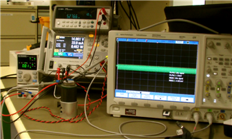
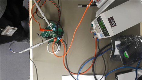
Figure 1 - The above image is of the original equipment configuration for the characterisation. |
Figure 2 - Picture above shows snapshot of data with non characterised load current | Test Equipment - The first look was the test equipment I was using (See Figure 1) and then how I was using it.
What I was using - As listed in the review all of the equipment is of excellent quality and in have been calibrated recently with the exception of the BK Precision. It is also difficult to comprehend that drifting even with the equipment I used would drift too far out to create issues. There was a concern with BK Precision 8354 as in the 30A mode the resolutions was quite small. This issue was considered very early in the review and as I was getting abnormally high efficiency the first thing was to consider was the current reading accurate in the steps of 100mA. I always considered the accuracy of the display a bit out and for the most part my assumptions (See Figure 2) were very close. |
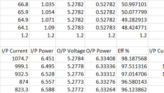
The first was to characterise the BK Precision. This proved that my assumptions were close but there still was a small amount of over estimating. The correct current reading were taken by using the DC Analyser and feeding it directly into the BK Precision.
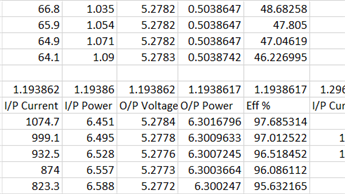
Figure 3 shows a snapshot showing the corrected load currents, changing in this instance from 1.2A, to 1.193862A. The precision of this was not incidental but instead using the logging feature on the DC Analyser I took reading every 10ms, then averaged out the results at each level to take in any noise affecting the measurement. Noise being uniform Gaussian, taking the average (approx 100 measurements) was the best approximation. The result added to the spreadsheet showed that any past reading of over 98% dropped to below 98%. The error deviation occurred at smaller load currents, whereas the margin of errors at higher load currents were so small it was almost not a factor at all. |
Figure 3 - Pictured above shows the same snapshot of data with a characterise BK Load current |
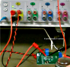
Figure 4 - Picture showing 4 wire sense lead to DC Analyser | DC Analyser - The DC Analyser is a very advanced product and has also been calibrated recently apart from the Spectrum Analysers in the lab the DC Analyser is one of the most used instruments. All products for CIRA all contain power supplies and integrity of operations is essential. Especially noise as the Square Kilometre Array (SKA) and the Murchison Widefield Array (MWA) requires some especially important considerations for RF noise especially when my work operates down to 30MHz. Some would have gotten wind that my leads were long from the power supply to the board. This is a viable assumption and was considered in the review. I failed to mention the DC Analyser also has a 4 wire function which compensate the wire length to produce an accurate input voltage directly on the board. This was one of my primary consideration in the test and was picked up early. |
Oscilloscope Leads - For those that were very aware of my original review, there is a problem with my measuring technique. The oscilloscope probe earth wire is too long and is becoming an antenna (See Figure 5). This not expected to be the main problem, but it is an area that requires attention. For this I will be working with a different probing method. Quite possibly I will be using 1 x probing and make probes for myself.
I expect that I will operate the input impedance to 50 ohms.
Power Supply leads - although as mentioned previously the DC Analyser has a 4 wire terminal (See Figure 4), I will consider the shortening and decreasing the gauge of the wire to as small as possible. One of the issues mentioned in the review is the terminals are quite small, therefore maybe difficult to connect the way I would like to. The output leads in the original testing were already quite large and difficult to terminate. Larger terminals would have been nice but a resolution can still be achieved. |
Figure 5 - Picture showing Oscilloscope probe measuring. |
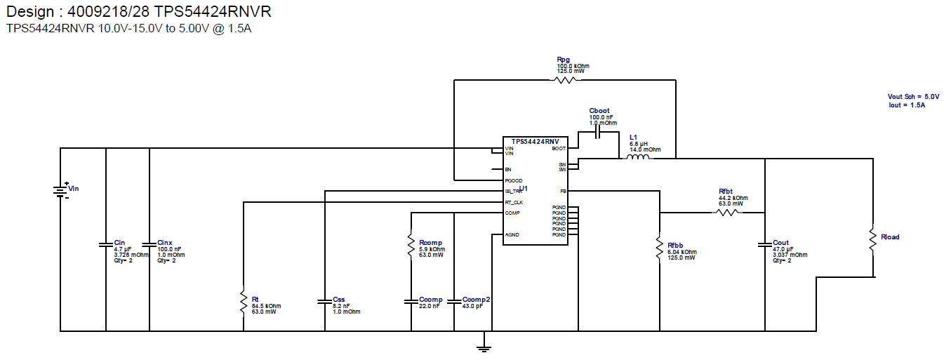
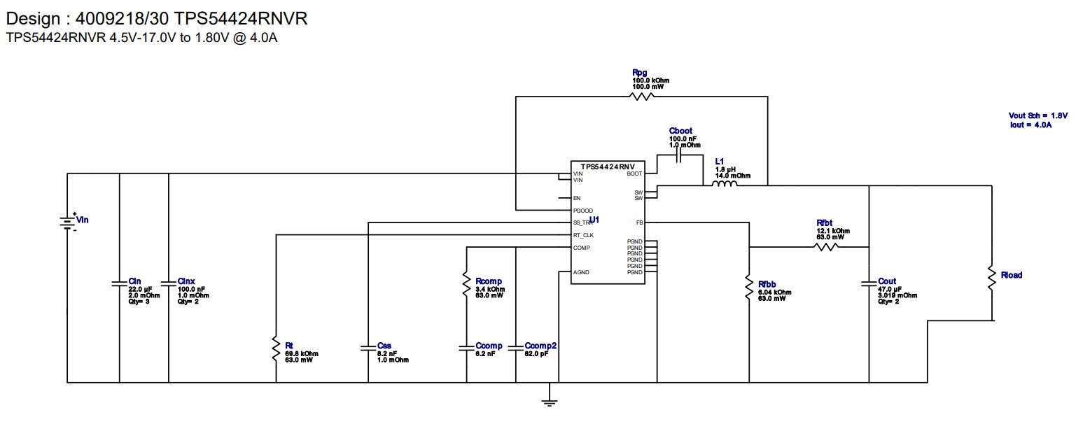
Figure 6 - Image of the updated schematic set to new parameters.
Figure 7 - Image of Original Schematic based on EVM design. | Circuit Components - This is the final aspect of the resolving errors, the 5.2V change only varied a single resistor to change the operating voltage. I already knew this was going to be a problem, but I wanted to quickly test the DC/DC Converter. For such a large ripple experienced is an issue on parameter called Boundary Condition Mode (BCM). This is the point in a buck converter where the ripple is set to an operating point to provide the smallest ripple and zero average current through the inductor and zero average current through the output capacitor. Notice that the output inductor will be changed from 1.8uH to 6.8uH. R(comp) and C(comp) will also be changed.
Instead of going through extensive theory in this blog post, instead I tightened my parameters in WEBENCH and this has recalculated the BOM list for the schematic. The design constraints now are input voltage of 10 - 15V set to typical battery high and low conditions. 1.5A, set for the expected maximum operating output current. The TPS54424, can go higher and is reserved for any future upgrades for the project, including LoRa and other modes of operation.
Quite a few components will need to be changed and the output parameters showed from WEBENCH that my ripple should be as low as 3mV. I will also add the UVLO, as the previous review allowed the converter to operate very poorly as a boost converter below 5V.
Figure 6 shows the components necessary to change to create a fully working 5V regulator. Figure 7 to the showing the components for the original design based on the EVM circuit parameters.
Further circuit parameters will be considered as well and ordering to start next week. |
Summary
This is not a review on the product but to notify the community things that can go wrong when testing. It will also be a great exercise to ensure the power supply will function the way it should be.
Part 1 -Step Down Converter EVM - Review
Part 3 -Step Down Converter EVM - Review Pt 3 - Components Arrived
Top Comments