


One day before the final day of the review on this DC/DC TPS54424/20 Converter and the parts arrived. As a summary of the day, it was a roaring success. I was unable to spend the time I wanted before the end of the review process but have managed to successfully replace the parts to obtain 5V. I cannot at this time finalise the test so I plugged it in to check some of the attributes.
Component Installation:
One of the challenges I experienced was the component selection. I had a WEBENCH design (tick), I had the EVM Design (tick) then came the painful correlation between the two.
The challenge was accepted and was finally able to correlate the parts required and the location to replace them. If the circuit was a lot more complex the circumstances would have been a lot different. The method I used was to write down the values required then place an arrow to the component annotation for replacement. example:
Definitely made the process a bit easier.
I did struggle soldering 4 components and this was partly due to the substantially large amount of copper on the DC I/P and O/P where the Weller tweezer tips I had on hand struggled to maintain thermal conductivity. Due to time running out I had to leave the I/P and O/P bypass components as is for the moment and will continue to look at the converter as I go.
YouTube Video link below:
Having a bad day at soldering 0603 components |
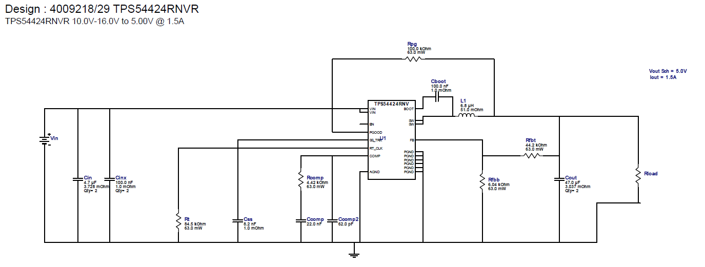
Circuit of the revised schematic.
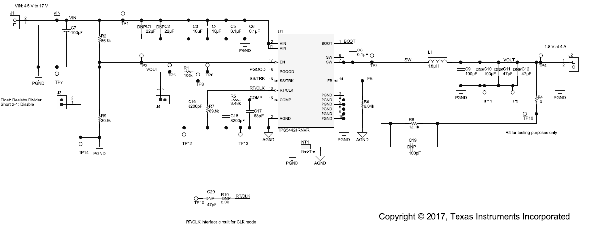
Circuit from TPS54424EVM-779 design documentation.
With the components installed it was getting late, but was determined to complete the testing. No full testing like was carried out during the initial review, just wasn't enough time. Instead I carried a number of regulation tests to ensure all was operational and the Output Ripple was good. |
The Test Setup:
Video of the test setup
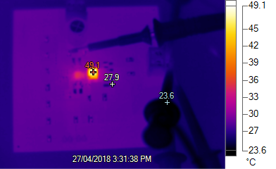
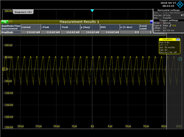
Thermal measurement taken after running for 30 minutes at 1.5A | As detailed in the previous blog entry (Step Down Converter EVM - Review Pt 2 - Resolving Errors ) one of the main issues I had to deal with was oscilloscope leads. The video on the left shows the configuration used in the recent test. All I can say is brilliant. WEBENCH stated that should experience 3mV ripple and noise. My result was 6mV. In saying that due to the soldering issue and inability to replace the I/P and O/P it is quite plausible that this is an effect. I was also unable to test surrounding main ripple which I believe will further reduce this level.
Overall very happy and feel confident that I can use this product for future use. I will continue to look further into the EVM and will post if viable any updates to the setup.
Although characterisation is not finalised, there are some specs obtained from the quick test. For the design 10 - 15V @ Imax of 1.5A the efficiency ranges from 90 - 93% line regulation and load regulation is very similar to my prior tests.
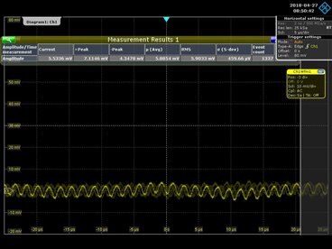
Two image Left: Input Ripple, within Spec, Right Output Ripple 6mV @ 12V I/P and 1.5A O/P |
Summary
I am very happy with this road test, though I have been servicing regulators, the opportunity to design or being part of the design is a big benefit. Experience is essential in engineering. Service takes an already designed approach and repairs any issues. Design engineering takes on a slightly different role and sometimes has challenges. I am fortunate enough to have servicing electronics for over 30 years now and with my recent studies combining my experience with new concepts has been essential. Many thanks to Element14 and Texas Instrument supporting me in my Final Year project and now feel confident that my project will have 20% more efficiency as a direct result of this EVM.
Part 1 - Step Down Converter EVM - Review
Part 2 - Step Down Converter EVM - Review Pt 2 - Resolving Errors
Hopefully more to come.
Top Comments