


This is the kick-off of my review of the Tektronix 3 Series MDO to cover the arrival of the unit, unboxing, review of kit contents, and a few basic tests.
Unboxing
The oscilloscope arrives in one rather large box, packed in expanding style foam covered in antistatic wrapping. The box is not heavy, but being so large I did find it a bit cumbersome to move around. It would have benefited from some handles or cutouts in the cardboard to aid with moving it. There are a few tears in the cardboard and one of the corners is slightly crushed, but nothing major, so it doesn't look like it has had too rough a journey.


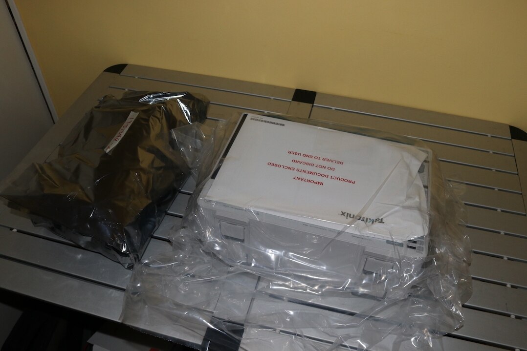
The oscilloscope itself was packaged in a clear plastic bag that was unsealed. The calibration certification was in the envelope you can see taped to the front of the oscilloscope. The rest of the accessories were within the antistatic bag just to the left of the oscilloscope on the bench.
Everything taken out of the bags and the bench surface is pretty much filled. The oscilloscope is supplied with 4 passive 500MHz probes, digital probes with optional grippers and pins for connections to the circuit, an adapter to covert the RF input to BNC, American style mains lead IEC connector, accessories bag that attaches to the handle, instruction leaflets for the probes, basic instruction manual, calibration certificate and packing contents list.

Paperwork supplied
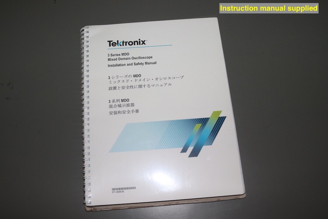
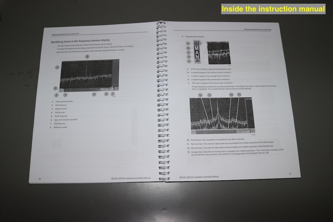
A brief look at the paperwork supplied with the 3 Series MDO. The main manual is spiral wound and supplied in three different languages. It has a glossy, full colour front cover, but the rest of the manual is in grey scale and almost looks like photocopy quality. The instructions are comprehensive and easy to understand.
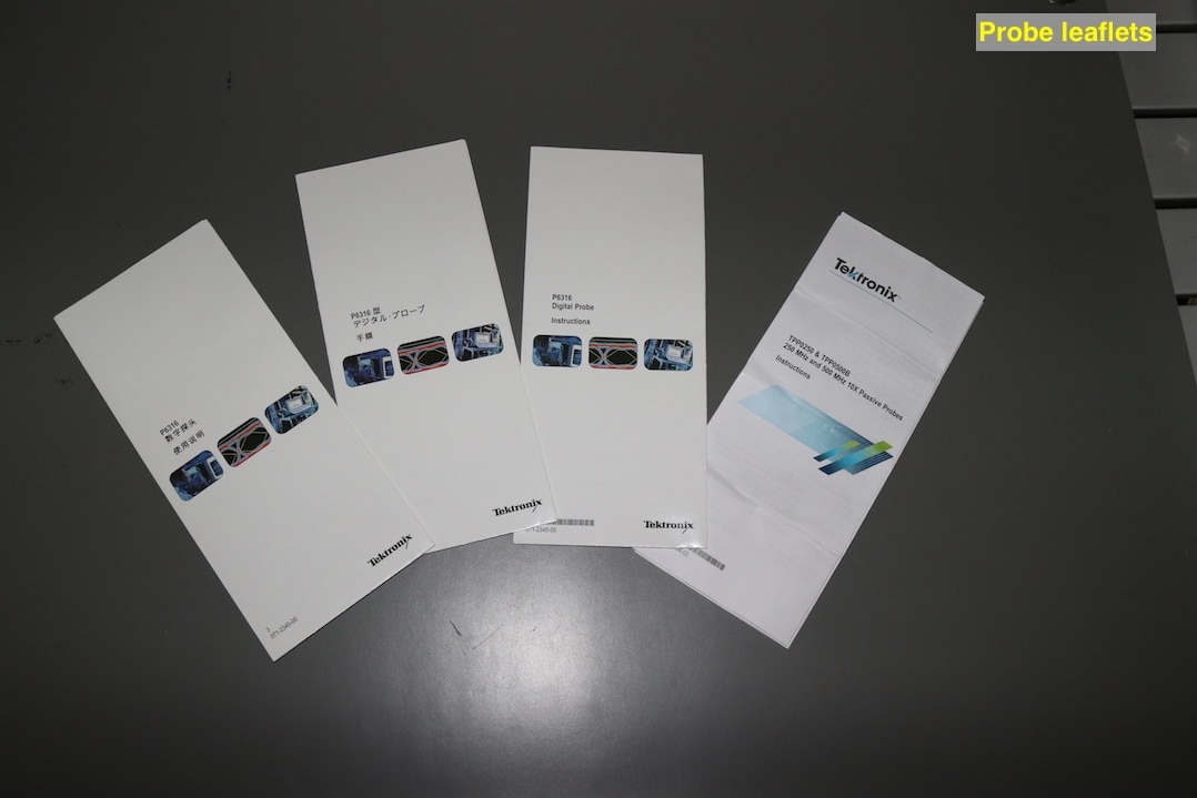
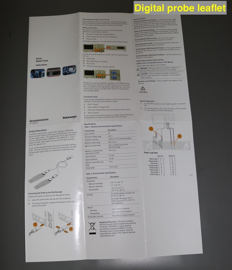
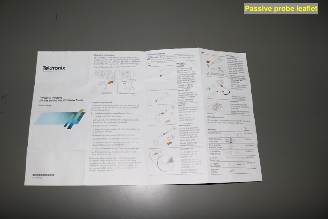
Leaflets for the digital probes are full colour glossy format and also supplied in the same three languages as the manual. The leaflet is for a P6316 digital lead and does not look lie it has been updated for use with the 3 Series MDO, has part of the instruction relate to an older scope series. Only one leaflet in English was supplied for the passive probes. This is also in colour, but is in matt paper.
| {gallery} Paperwork supplied |
|---|
Scope basic instruction manual |
Inside the manual |
Three digital and one passive probe leaflets |
Leaflet for digital probe |
Leaflet for passive probe |
Calibration documentation |
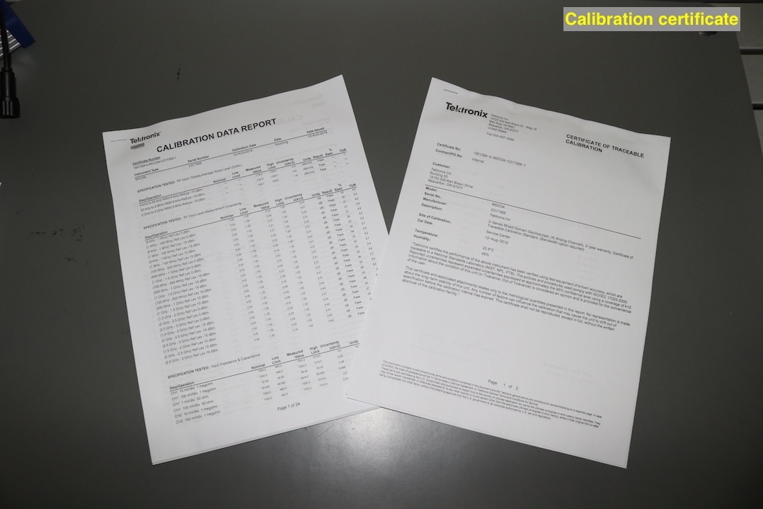
The calibration certificate is very good with 34 pages of test data accompanied with an overview document cover the traceable calibration requirements.
Passive Probes
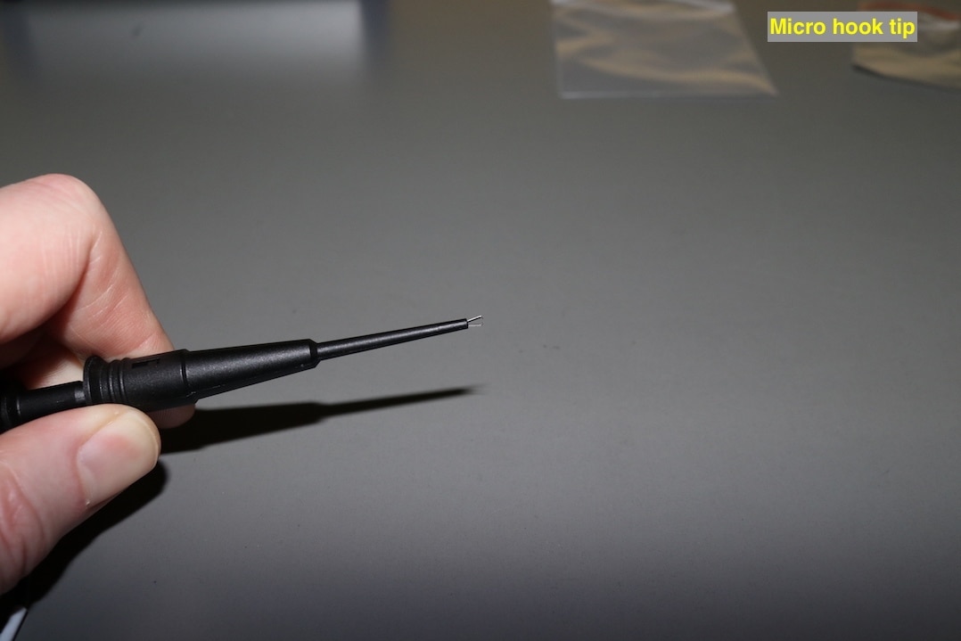
Four 500MHz passive probes are supplied, each in its own sealable clear plastic wallet and comes with four ground connection springs, a IC cap, a regular hook tip, a micro hook tip and a crocodile earth lead. A spare crocodile earth lead, micro clip earth lead and colour identification rings were supplied in a separate bag.
| {gallery} Passive Probes |
|---|
Passive probe kit and wallet |
Standard grabber probe tip |
Micro grabber probe tip |
Ground springs |
Passive probe extras |
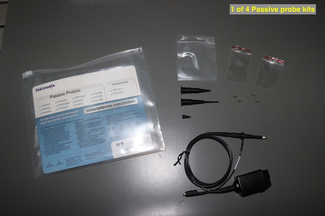
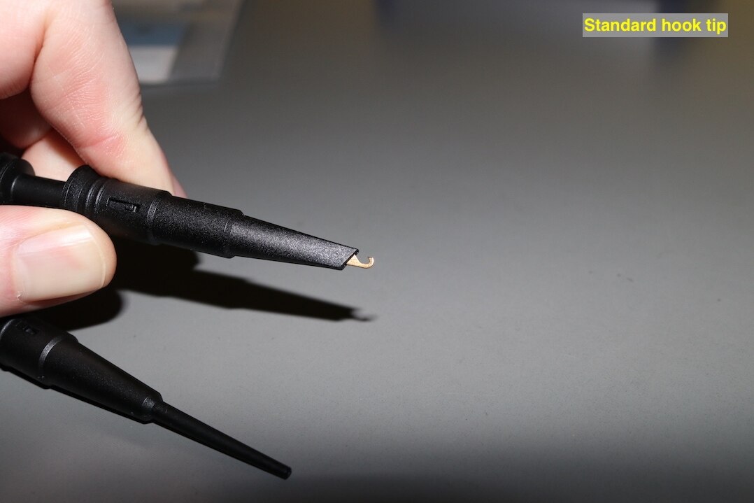


The probes are of excellent quality and are very slim to aid in carrying out probing on crowded PCBs. The probe has a push fit for the BNC connector in the scope and is retained into the connection by a spring loaded clip on the plastic case of the probe. The probes are fixed x10 and compensation is carried out through a menu option in the oscilloscope.
The earth leads clip securely to the probe body and the mini crocodile clips at the other end is strong and of a typical size for oscilloscope probes that I have seen.
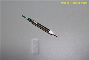
Initially I only looked at one of the passive probes and unfortunately, as I progressed with using the oscilloscope and looked at the other passive probes, I realised that the other three probes had all come with a fixed tip that can be swapped for the spring-loaded tip installed in the probe when it arrives. Somehow, I had managed to pick out the one out of the four that had this fixed tip missing.

Digital Probes
A single digital port is on the front of the oscilloscope that accepts a 16 channel probe. The probe comes in three parts, a 16 channel lead that breaks out into two header connectors and two individual headers each with eight digital inputs and two ground connections. Each lead on the header has its own colour code. A set of micro hook tips and pins are supplied for each of the headers.
| {gallery} Digital Probes |
|---|
Parts of the digital probes |
One of the digital probe headers |
Header and micro hooks |
Close up of header leads showing identification |
Digital probe tips |

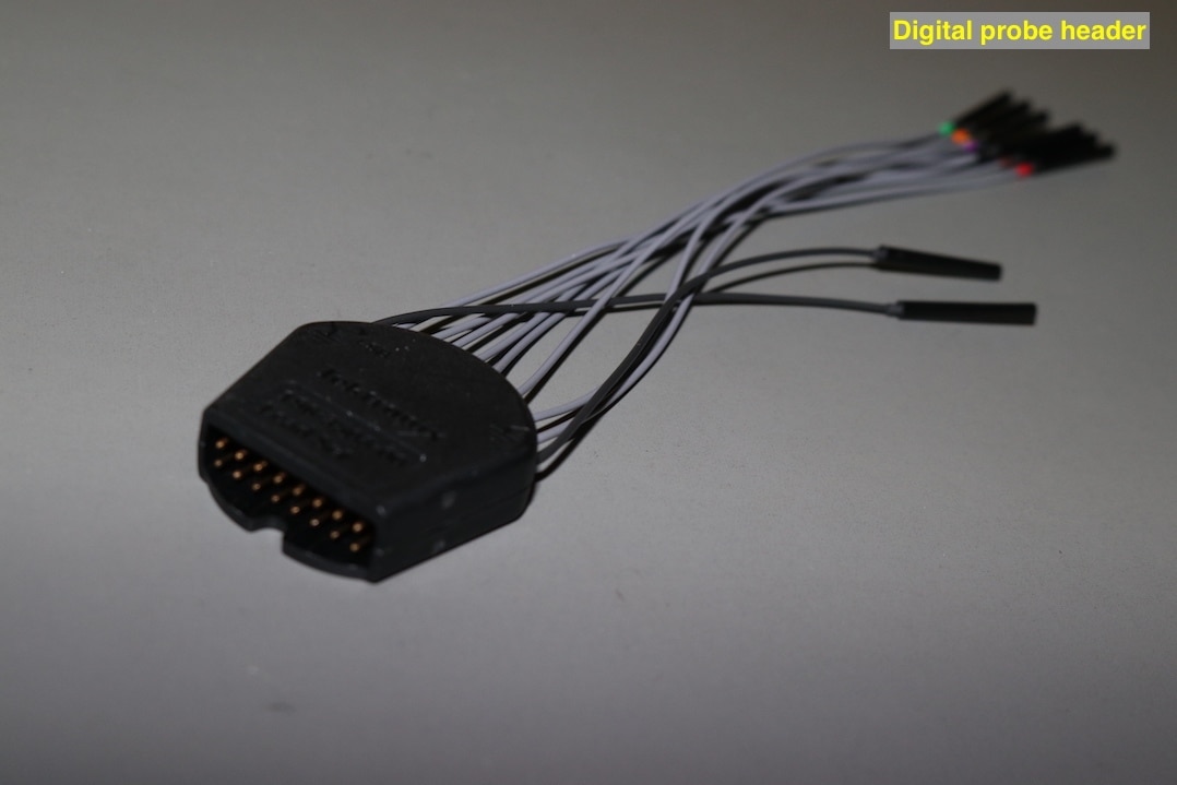

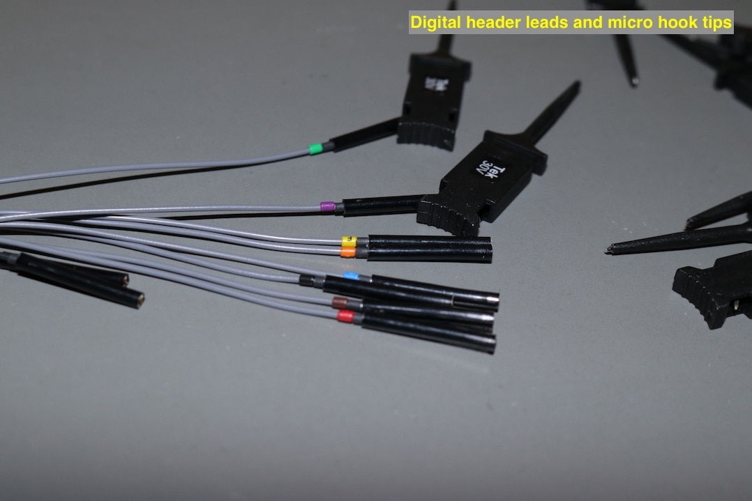
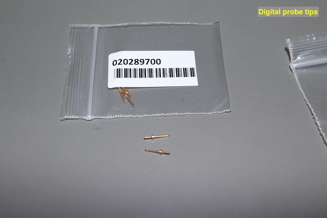
The digital probe looks to be well made. The micro hooks and probe tips clip firmly into the header leads and do not feel that they would come adrift during testing. I do find the probe tips widely to utilise and stored in the little ziplock bags, I can imagine that the will easily get spilt and lost. I think I will look for another storage method for these. the colour marking on the leads are clip on plastic rings, that may come off with use of the probes.
There is a problem though. The interconnecting lead between the digital probe headers and the oscilloscope has not been supplied within the package.
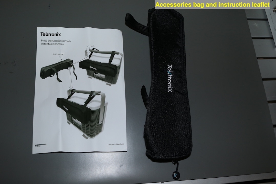
To round off the accessories, a pouch is supplied to store them in that will attach around the handle of the oscilloscope. This is a nice touch and often not considered by other manufacturer's oscilloscopes I have purchased. How well it will hold the probes and accessories remains to be seen, as the passive probes will have to be removed from their wallets to fit inside the bag, that then leaves their accessories reliant upon the ziplock bags to remain tidy.
Build quality of oscilloscope

The scope is quite a size and its appearance is dominated by the large touch screen, with the input connections below the screen and controls placed to the right of the screen. All the functions are clearly labeled and are easy to identify.
At the rear of the case, the mains input, waveform generator output, aux output, LAN, USB Device and Host and an HDMI output connections. There is also a Kensington lock slot to allow the scope to be secured.
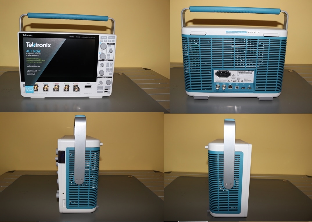
Down the righthand side is the probe compensation output test points and a 4mm earth socket. The lefthand side is void of any connection points.
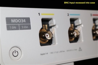
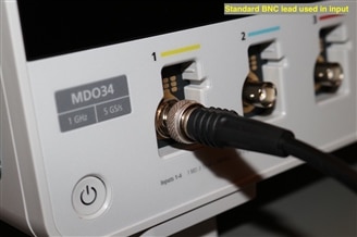
The input sockets at the front are recessed, by the looks specifically for compatibility with their own probes, but this does not prevent the use of leads with standard BNC connectors if required.
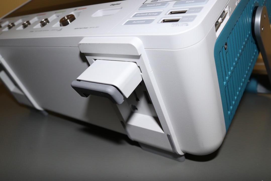
The handle also acts as part of tilt stand. It has a very positive feel to its movement, but does not require excessive force in my opinion. To complement the lower angle of the handle, the two from feet under the scope will flip out to allow the scope to sit at a comfortable viewing angle. These feet have been set to sit flat at the same angle provided by the handle.

To further assist with the angle, the feet have a bottom spring-loaded section seen below.
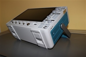
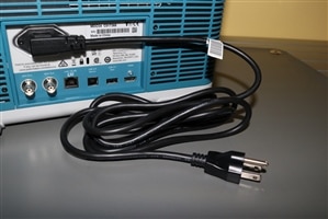
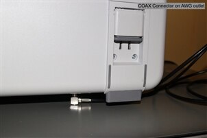
If desired, the scope handle can be raised to its upper position and then the unit can be tilted even further and still remains stable. A final option is to site the scope on its back completely, where all four feet at the rear of the case now support the scope. To allow the scope to be laid down, a mains lead with a right-angled IEC connector is supplied. Unfortunately a right-angled COAX on the AWG connector on the rear of the oscilloscope does block the scope from sitting on its feet when laid down.
Overall, the build is quite robust and has some nicely thought features. However, I then started to notice some cosmetic damage as I looked further around the unit.
The seam around the front edge, is not even all of the way around. At one of the top corners it does not line up with the rest of the case. In some areas the seam is tight together, in others, there is a little movement as though the case has not been fully screwed together.
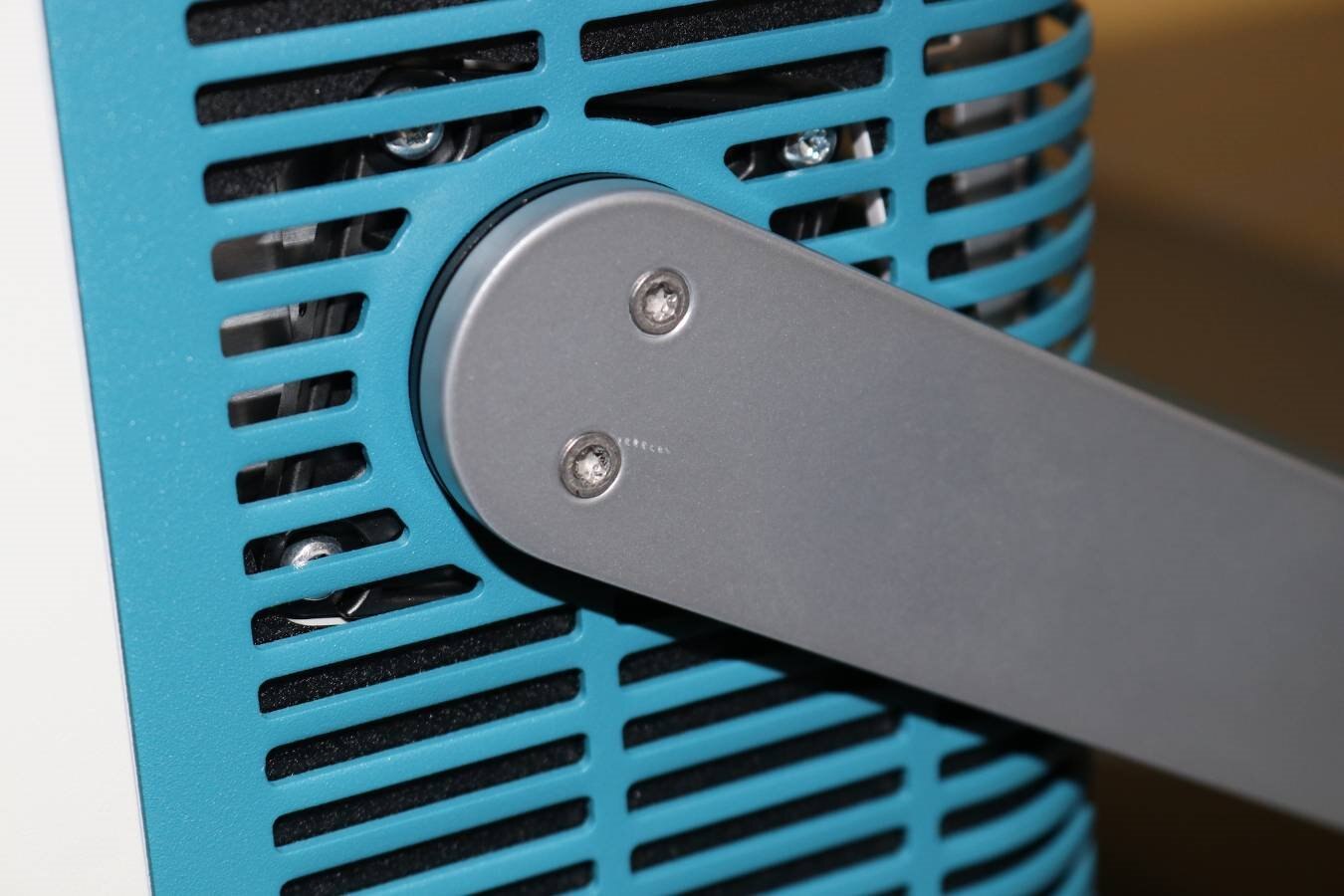
Looking at the handle, there are scratches around one of the securing screws indicative of where a power tool has been used to tighten the screws and has slipped out. A close look at the head of some of the screws shows damage to the torx shape, made by either using the wrong tool or not fully seating the correct tool when tightening the screws.
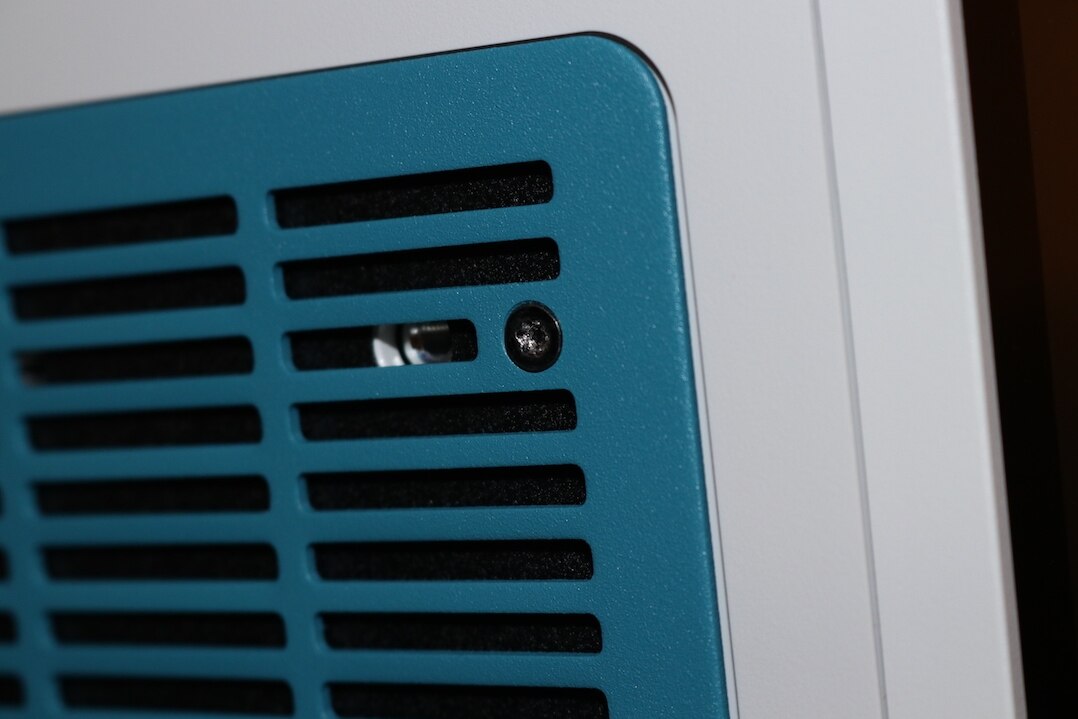
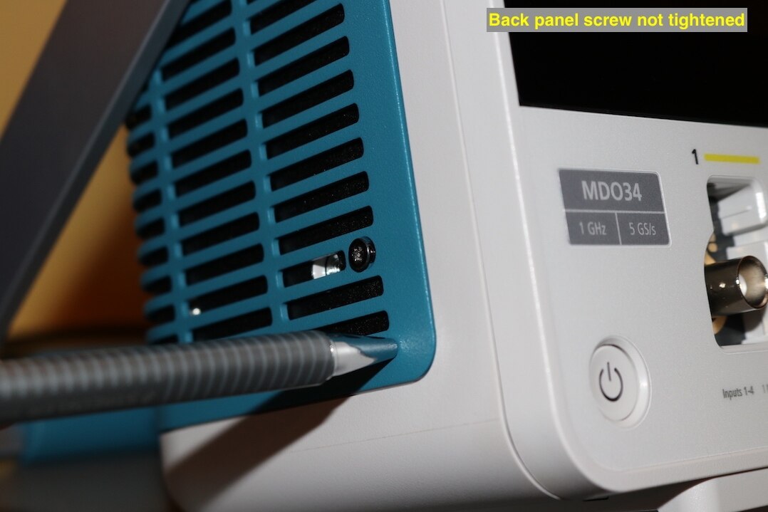
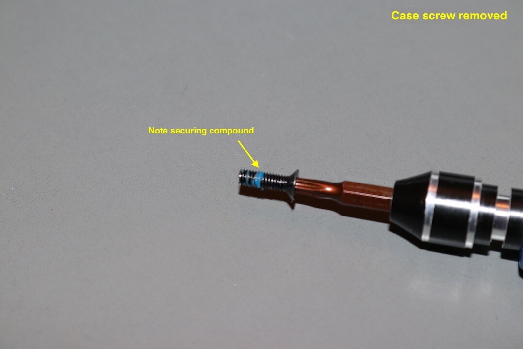
The blue cover at the rear was found to be loose in three out of the four corners, this was worse on the lefthand side. The screws again looked as though the torx heads had some damage. The screws securing the cover were found to be tight, but not driven fully home. Removal of one of the screws showed a blue securing compound around the threads. Presumably, the screws had been tightened up onto the compound, but not to fully tighten the cover.
| {gallery} Cosmetic damage |
|---|
Damaged torx head |
Loose rear panel |
Screw not tightened onto cover |
Securing compound on lid screw |

All of this is cosmetic, and to some may seem trivial, as it does not affect the functionality of the scope, and no doubt the scope will pick up some scars throughout its working life. However, this is a unit from a top manufacturer, carrying a premium price in the region of 15,000 USD. For that kind of price and manufacturer name, I would expect this unit to start out in premium condition. The price is in the region of some new small cars and certainly motor bikes, if they arrived with loose parts, damaged screws and scratches, it wouldn't be acceptable, and I don't think it should be with this oscilloscope either.
I am in two minds about a teardown of the unit. This is a very powerful piece of test apparatus with an independent traceable calibration, that would be voided by dismantling the unit. I also generally carry out performance tests prior to a teardown and repeat the same tests afterwards to show that there are no issues. I don't really have test apparatus to carry out the full range of tests that this unit would warrant. On the other hand though, the quality issues surrounding the build, gives me concerns about what may be hidden away out of sight inside the unit. There is no definite cause of the failure of the unit to start-up, but intermittent operation is typical of poor or loose connections. I have discussed this with Tektronix and they have asked me not to carry out a teardown as the unit is to be returned to them, so I will respect that.
Start-up
This gets it own little section as I have had some issues with this aspect. The first start-up was very slow, in the region of two minutes, after this I could not get the scope to start-up at all, it would just hang at the initial Tektronix screen and make faint clicking noises every few seconds.
I left the unit for a couple of days and then gave the unit a good visual examination using a torch through the external grille to see if there were any noticeable issues to the eyes or ears that could be responsible for an intermittent start-up. On trying the scope after this inspection, it did start-up taking around 70 seconds to do so and has done this consistently since then. The faint clicking noises can still be heard on an intermittent basis.
To me this seems like quite a slow start-up, much slower than any other instrument I have. If the scope is to be used in a workshop / laboratory environment, started once a day and left running it may not be too much of an issue. When used on an intermittent basis, I can see it leading to frustration. I had planned to take this out to sites with me to assist with data collections on generators. A site with seven generators with two tests per generator that requires re-location after each test, will see the scope started 14 times.
Scope Probe Compensation
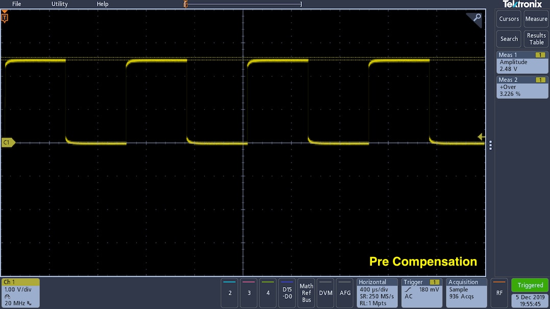
As previously mentioned probe compensation is carried out from the menu for that particular channel.
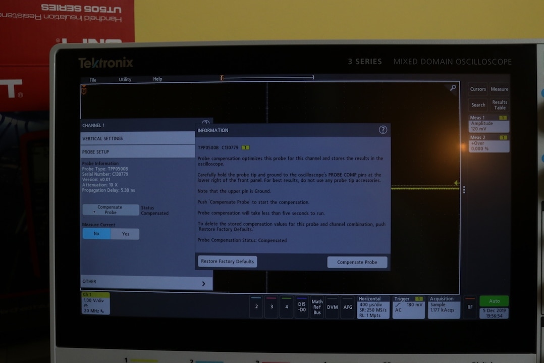
Once applied, the scope remembers this adjustment, for this particular channel and probe. A button to restore default compensation from the factory is available to reset a particular probe and channel setup. The procedure to compensate the probe is quick and easy to carry out.

Insulation Tester Measurements
I carried out some tests measuring the output of one or two insulation testers I seem to have lying around. To do this requires the use of a high voltage probe, I have one that is just a home built resistive divider and another that is a manufactured differential probe.
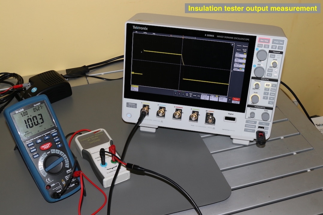
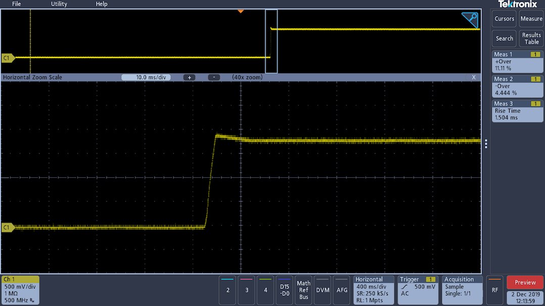
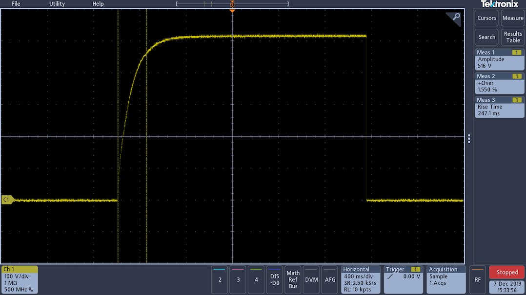
The scope has a nice automatic overshoot measurement to aid with the analysis of the insulation tester output as well as the other expected measurement functions for a waveform. The output of this is displayed as a percentage instead of an actual voltage value. I did also find that the number of measurements was limited to four. Usually adequate if just one single channel is in use, but may become restrictive if more channels are utilised, as the limitation of four is overall and not per channel.

A zoom window can be quickly displayed utilising the magnifying glass in the top right hand corner of the screen, The touch screen allow easy manipulation of the window and the section of the waveform displayed.
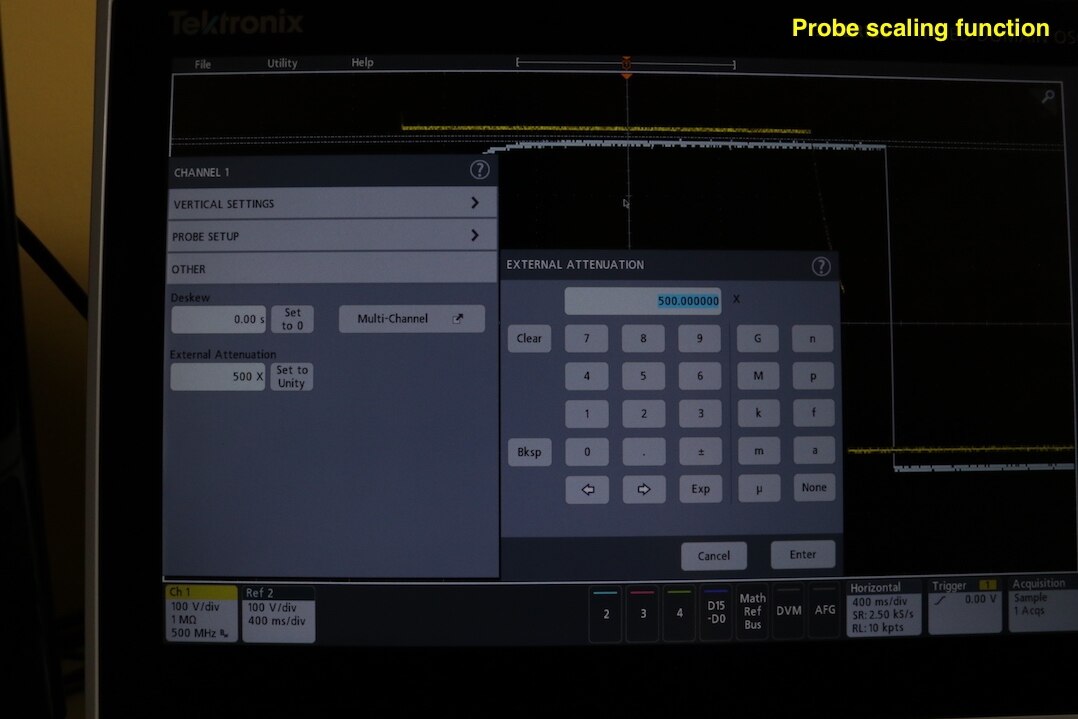
With the use of the differential probe or resistive divider, I would usually utilise a scaling factor, so that the measurement displayed on the screen represented the actual output level of the insulation tester and not the voltage of the differential probe. Unfortunately, initially I could not find this function within the probe menu, so some of the readings are scaled up to the expected voltage. Tektronix have labelled this function as External Attenuation.
There are also four reference traces available which could be used to recall a waveform saved to the scope. This allowed me an easy way to visually compare outputs from two different insulation testers. Each waveform can also be given an on screen label to help identify them. I could not find a way to move these labels from there default positions, so with the waveforms of the two testers line up for comparison, the the label for the reference waveform becomes hidden.
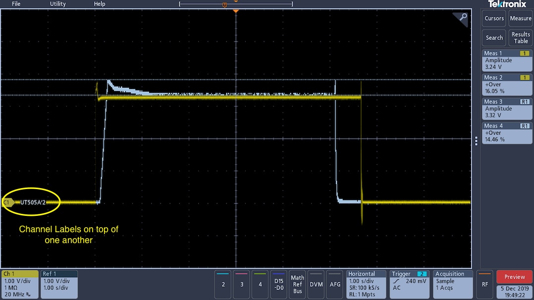
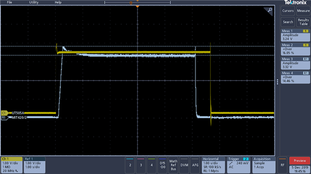
Of course the waveforms can easily be split to reveal both labels.
Scaling of the input is found at the bottom of the probe menu under 'other'. A numerical pad can then be used to set the required scaling factor under the external attenuation option. There is also a quick button to set this back to zero.
The output voltages are then displayed with the expected values as seen below.
| {gallery} Scaled voltage readings |
|---|
Output voltage of Brymen scaled to 500V |
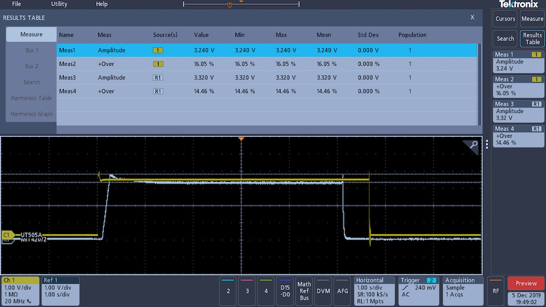
Brymen and Dilog output overshoot comparison |

As well as displaying the measurements in the side bar on the right of the screen, a measurement table, that provides more statistical data can be turned on and off.
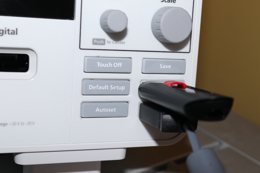
All of the screenshots are saved from the oscilloscope direct to a USB drive, using either the 'save' function from the 'file' menu or the quick save button on the keypad directly above the USB ports. The two front USB ports were found to be spaced nicely, to allow use of an external mouse in one and a USB stick in the other without fouling as seen below.
RF Measurements
The 3 Series MDO has a specific input for a RF Spectrum analyser and since the DL9307 and MG302 insulation testers have an RF wireless communications module in them, this seemed like a perfect opportunity to take a look at the waveforms, especially as the MG302 wireless communication has failed.
Once the RF input is selected, all other input channels are switched off. The menus allow the trace captured to be centred on the screen and the span of the signal analysed adjusted to suit. The measurements were made with a very basic pickup antenna.
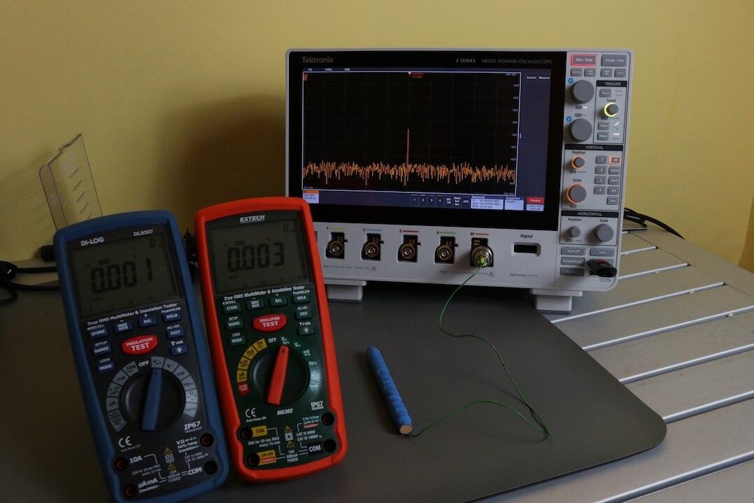
The output of the DL9307 was measured as 914.9 MHz, whilst the MG302 was measured as 433.9 MHz, a quick explanation as to why the receivers were not swappable.

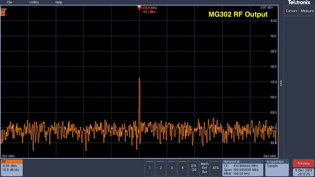
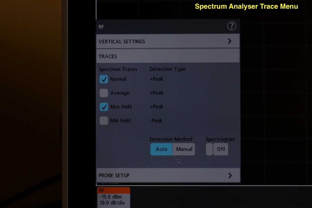
The spectrum analyser offers four traces that can be displayed on the same screen of normal, average, max hold and min hold, and three different measurements that can be displayed one at a time of Channel power, Adjacent channel power ratio and Occupied bandwidth. I carried out these measurements on the MG302 without any issue.
| {gallery} Spectrum analyser traces |
|---|
Spectrum analyser trace menu |
Power measurement of channel |
Adjacent channel power ration measurement |
Occupied bandwidth measurement |
Normal and maximum hold traces displayed |
Spectogram display |


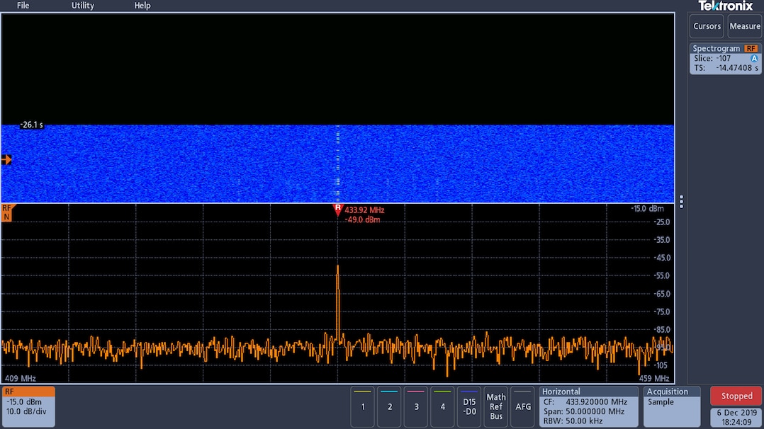
The spectrum analyser also gives an option to display a spectrogram of the trace. Once completed or stopped, the spectrogram list can be moved through using the control to display any specific elements of interest.
USB Analysis
A trial license for the protocol decoding is also included with the oscilloscope, so I took a look at the USB function to track what was happening on the output of the receiver for both the DL9307 and MG302 testers.
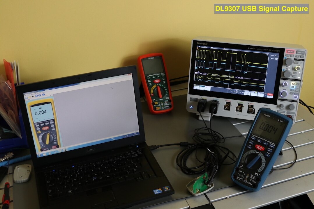
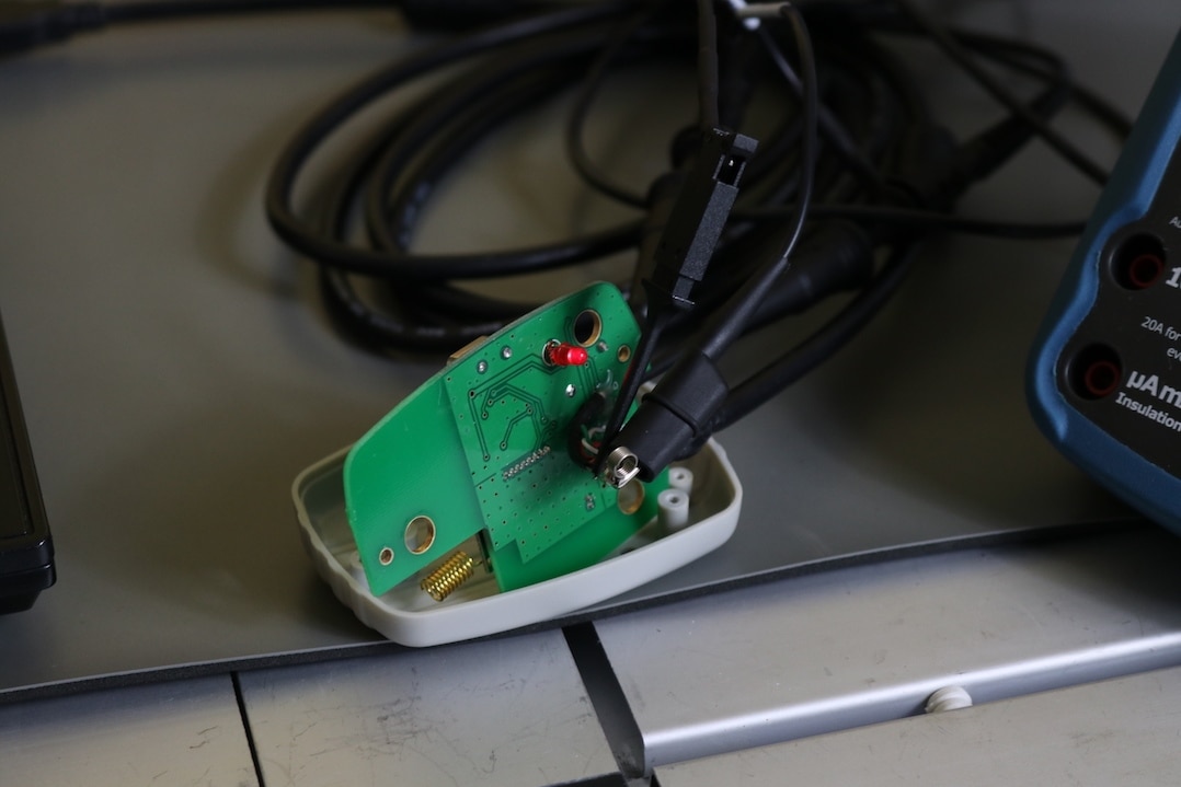
The tester was set up to transmit AC voltage readings to the laptop running the data collection software. I had to break open the receivers to get to the USB connections to probe them as I do not have any USB breakout boxes. This resulted in some poor probing techniques, leading to noise on the traces captured by the oscilloscope.
The USB signal for the DL9307 can be seen below. The scope was set up with Channel 1 reading D+ and Channel 2 reading D-. The USB decoding was then added via the 'Bus' menu to analyse the signal.
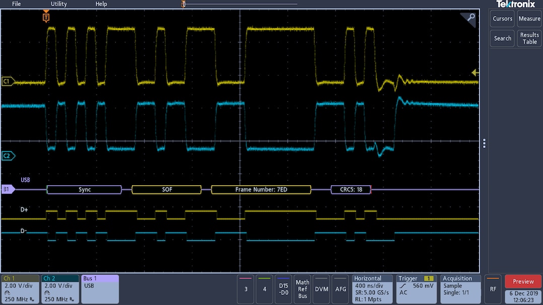
You can see the noise on the D- line of the USB traces for the MG302 in the picture below, I believe due to a poor ground connection.

The decoding of the signal for the MG302 looks to be different to the DL9307, yet they utilise the same software and drivers. The MG302 will no longer communicate with the laptop, presumably the answer lies somewhere within the signals captured, but I have a lot of reading to do first to gain an understanding of the USB protocol and what each element means. The 3 Series however, has added some very useful tools to my kitbag for looking at the issues with these two meters.
HDMI Output and remote LAN operation
If the scope screen is not big enough for you, then the 3 Series also offers an HDMI output on the back of the unit for connection to an external monitor. I had a quick look at this, with the intention to find if there was any lag in the update between the scope screen and the HDMI display. I connected one channel to the waveform generator output and adjusted the signal a few times. There is no real discernible lag between the two that would cause anyone concerns and it is a nice feature to have if you were running demonstrations for people.
I also connected up the oscilloscope to a laptop via a LAN connection to see if there is any lag with this operation. There is a built in web browser package that is very fast to start. Changing the signals around with this test setup did reveal a noticeable lag between the oscilloscope display and the laptop display, but overall I feel that it could be easily lived with. I did notice that when connected remotely, the oscilloscope could still be controlled with the local buttons, which may be an issue for some.
Transport case
Not strictly part of this roadtest as I have brought this specially as I plan to take the 3 Series to a couple of sites to carry out measurements on generators and cabling systems. Tektronix offer both a soft carry case and a hard carry case. I have opted for the soft carry case, this also comes with a front cover that clips in place over the front of the scope to provide protection to the controls and screen.
| {gallery} Padded Case |
|---|
Padded case for 3 Series MDO |
Scope with cover fitted to front |
Scope inside padded case |
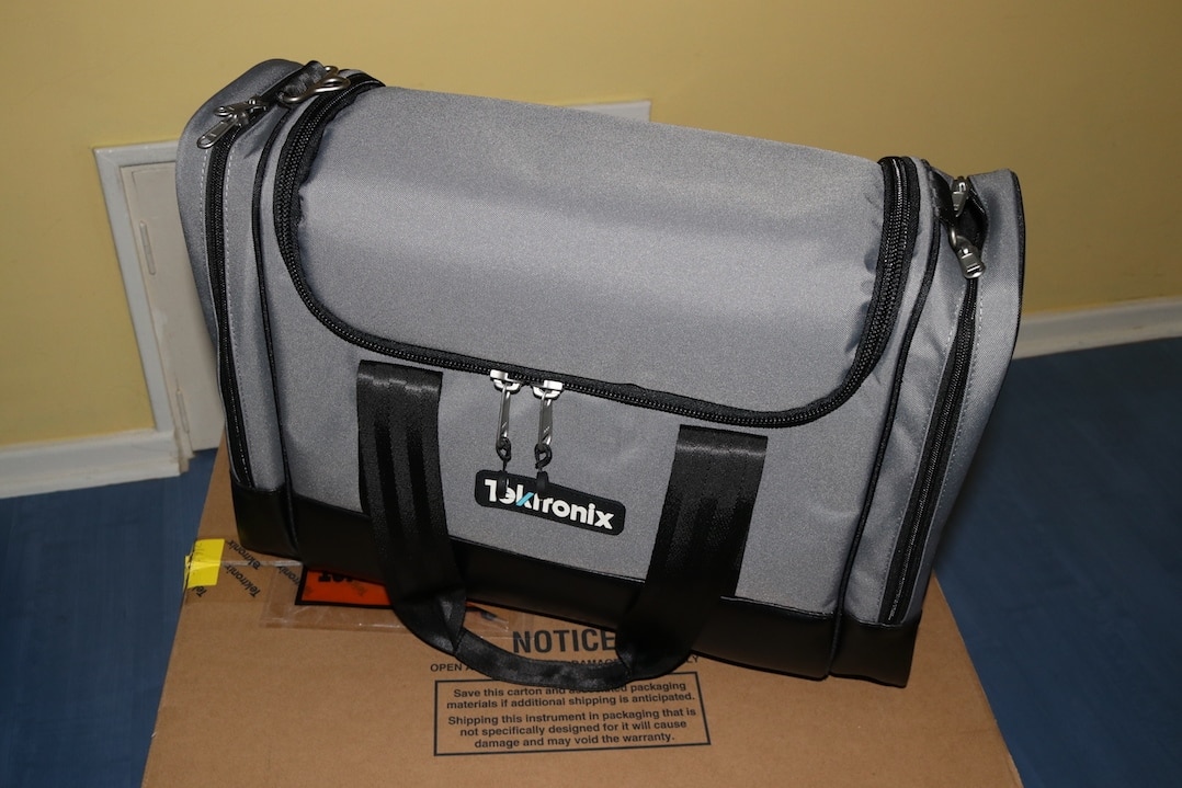
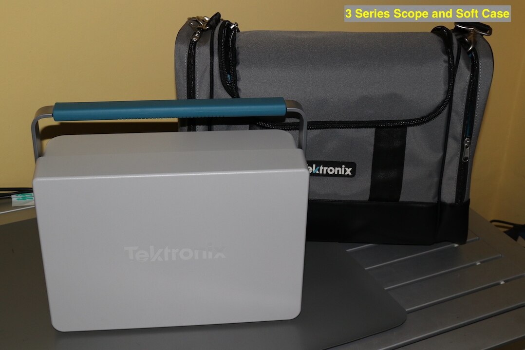

The cover fits securely onto the scope clipping into the side vents. The padded case is good quality with metal zippers and shoulder strap clips. The shoulder strap is easily adjustable and there is also a carry handle either side that join together over the top through a velcro wrap around handle. A side pocket at each end of the case offer extra storage for leads.
Conclusions
This initial blog was just to get a feel for how the 3 Series MDO operates and get a view of some of its functionality. It is obviously a very powerful piece of test equipment, but comes with a very friendly user interface that one can learn within a very short space of time. There are multiple ways to select functions, but they tend to compliment one another instead of creating confusion about how to do certain operations.
I can see the multifunction instrumentation being a main attraction of this unit, it makes it a very versatile unit and handy for someone with the need of a scope, spectrum analyser and waveform generator. Couple this with the software options available make it one of the most versatile piece of test apparatus I have ever reviewed or worked with.
I am quite disappointed in the build quality of this unit. I do not know if this is typical of Tektronix, or if I have been unfortunate enough to get the 'Friday afternoon' build. On top of this though there is the addition of a couple of missing items.
It seems to have a couple of discrepancies for my particular requirements. The limitation to four overall measurements may become a hinderance. I can see the boot-up time leading to frustration and to my knowledge is also significantly slower than the units produced by their main competition. I will see how I get on with these aspects as I start to utilise the oscilloscope out on plants.
There is still a lot more for me to learn with this oscilloscope that I have not touched in this introduction, and I hope to take a look at some of these as I progress onto my testing program offered in my proposal.
I am currently using the roadtest unit and a demo unit supplied by Tektronix as they wish to have the roadtest unit returned to them for inspection to see if there are any issues. Given the nature and cost of this unit, I am reluctant to take the demo unit out onto sites as I had planned, so most of the testing is bench based at the moment, until either a new unit is received or the issues resolved with the roadtest unit. Whilst I still have the roadtest unit though, I will take it out to site, as it seems to be behaving at the moment.
Top Comments