element14 Community
element14 Community
    Register Log In
  • Site
  • Search
  • Log In Register
  • Community Hub
    Community Hub
    • What's New on element14
    • Feedback and Support
    • Benefits of Membership
    • Personal Blogs
    • Members Area
    • Achievement Levels
  • Learn
    Learn
    • Ask an Expert
    • eBooks
    • element14 presents
    • Learning Center
    • Tech Spotlight
    • STEM Academy
    • Webinars, Training and Events
    • Learning Groups
  • Technologies
    Technologies
    • 3D Printing
    • FPGA
    • Industrial Automation
    • Internet of Things
    • Power & Energy
    • Sensors
    • Technology Groups
  • Challenges & Projects
    Challenges & Projects
    • Design Challenges
    • element14 presents Projects
    • Project14
    • Arduino Projects
    • Raspberry Pi Projects
    • Project Groups
  • Products
    Products
    • Arduino
    • Avnet & Tria Boards Community
    • Dev Tools
    • Manufacturers
    • Multicomp Pro
    • Product Groups
    • Raspberry Pi
    • RoadTests & Reviews
  • About Us
    About the element14 Community
  • Store
    Store
    • Visit Your Store
    • Choose another store...
      • Europe
      •  Austria (German)
      •  Belgium (Dutch, French)
      •  Bulgaria (Bulgarian)
      •  Czech Republic (Czech)
      •  Denmark (Danish)
      •  Estonia (Estonian)
      •  Finland (Finnish)
      •  France (French)
      •  Germany (German)
      •  Hungary (Hungarian)
      •  Ireland
      •  Israel
      •  Italy (Italian)
      •  Latvia (Latvian)
      •  
      •  Lithuania (Lithuanian)
      •  Netherlands (Dutch)
      •  Norway (Norwegian)
      •  Poland (Polish)
      •  Portugal (Portuguese)
      •  Romania (Romanian)
      •  Russia (Russian)
      •  Slovakia (Slovak)
      •  Slovenia (Slovenian)
      •  Spain (Spanish)
      •  Sweden (Swedish)
      •  Switzerland(German, French)
      •  Turkey (Turkish)
      •  United Kingdom
      • Asia Pacific
      •  Australia
      •  China
      •  Hong Kong
      •  India
      •  Japan
      •  Korea (Korean)
      •  Malaysia
      •  New Zealand
      •  Philippines
      •  Singapore
      •  Taiwan
      •  Thailand (Thai)
      •  Vietnam
      • Americas
      •  Brazil (Portuguese)
      •  Canada
      •  Mexico (Spanish)
      •  United States
      Can't find the country/region you're looking for? Visit our export site or find a local distributor.
  • Translate
  • Profile
  • Settings
RoadTests & Reviews
  • Products
  • More
RoadTests & Reviews
Review Blogs TI and Würth Elektronik LED RoadTest+ - Circuit Crafting - 8/10
  • Blogs
  • RoadTest Forum
  • Documents
  • RoadTests
  • Reviews
  • Polls
  • Files
  • Members
  • Sub-Groups
  • More
  • Cancel
  • New
Join RoadTests & Reviews to participate - click to join for free!
  • Share
  • More
  • Cancel
  • Author Author: tonyboubady
  • Date Created: 10 Jan 2016 2:15 PM Date Created
  • Views 878 views
  • Likes 2 likes
  • Comments 11 comments
Related
Recommended
  • RoadTest
  • ledroadtestplus
  • würth
  • we
  • elektronik
  • texas_instruments
  • ti

TI and Würth Elektronik LED RoadTest+ - Circuit Crafting - 8/10

tonyboubady
tonyboubady
10 Jan 2016

Update: I am working on the soldering WE's SMD LEDs with my tricks and ideas. You know what? it really looks cool and works great...but... I don't think I can do the thermal protection with the board I have etched, it seems super hard and as well the amount of LEDs with thermal holes seems almost snap off point of the board, too close and board is getting weak...My design could work with professional PCB with 3 layers. I am going to finish this project up for demonstration purpose only...will update on next post...


Hello, here I am again with some update image


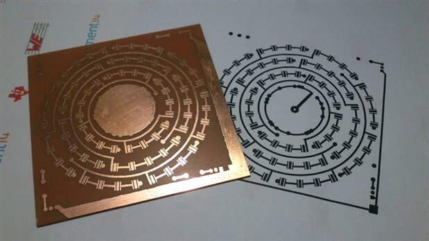
I have managed to finish the etching process today, successfully... and I am happy about it. I started with printing my circuit design with laser print and I am not using any glossy paper, it was a quite a story that I can't take laser print with glossy paper here, so I have figured out a way to do it with regular A4 paper and some tricks image


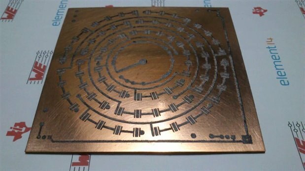
This is my successful toner transfer to copper clad board...


image


I had to do some adjustment with permanent marker pen (Sharpie), yeah! that's how we call it here in India.


image


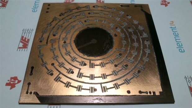
Now it's time to etch the board with Ferric Chloride - FeCl3 ... and this is the result.


image


It's not the perfect one but it does the job...


image


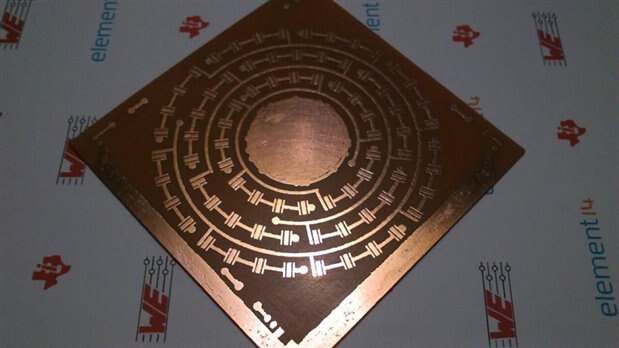
I am happy about the result... even less than half a millimetre space has been etched, really cool... the next process is soldering the SMD LEDs, WOW!!! but I have some IDEA to do it without using hot air gun, soldier paste with oven etc etc... image. I will post my process in next coming days.

  • Sign in to reply

Top Comments

  • tomaja
    tomaja over 10 years ago in reply to shabaz +3
    Hi shabaz , Do you think he could use solder just to reach the bottom side of the board and then thermal paste to connect to heatsink? (I originally planned to do that, but later I found suitable Aluminium…
  • shabaz
    shabaz over 10 years ago +2
    Hi Antony, I'd hate for you to solder on all those LEDs, and then find out, but have you checked what heatsinking requirements are needed? If these are LEDs with 350mA or higher current consumption, then…
  • shabaz
    shabaz over 10 years ago in reply to tomaja +2
    Hi tomaja Interesting idea, it may be possible, if it is filled with solder from the underside somehow and then flipped over and sanded/polished flat. There is a product which would have been suitable…
  • dougw
    dougw over 10 years ago

    Hi Antony,

    Aesthetically a very nice looking design and good work on successfully etching the traces. As you have realized, this design imposes significant limitations on how much current can be used, but it will still look very cool.

    Here are some references that might help figure out how much power your design can handle:

    http://focus.ti.com/download/trng/docs/seminar/Topic%2010%20-%20Thermal%20Design%20Consideration%20for%20Surface%20Mount…


    Thermal Vias – A Packaging Engineer’s Best Friend « Electronics Cooling Magazine – Focused on Thermal Management, TIMs…


    It takes a lot of work to accurately figure out ,but you can quickly get a rough estimate for how much power your design can handle. If this is satisfactory, you can do a test to see exactly how much power is possible. Simply populate the card and slowly increase current until the LEDs get to a maximum safe temperature.


    Doug

    • Cancel
    • Vote Up +1 Vote Down
    • Sign in to reply
    • More
    • Cancel
  • tomaja
    tomaja over 10 years ago in reply to shabaz

    Hi shabaz,

    Do you think he could use solder just to reach the bottom side of the board and then thermal paste to connect to heatsink?

    (I originally planned to do that, but later I found suitable Aluminium PCB's on eBay)

    • Cancel
    • Vote Up +3 Vote Down
    • Sign in to reply
    • More
    • Cancel
  • tonyboubady
    tonyboubady over 10 years ago in reply to shabaz

    I have tried something called oxidation with aluminium to solder...and I have did the solder successfully before. It's not my idea though, I have read some article about it from web and tried that...and yes it's all about how fast I drill the PCB image...of course it's a challenge to handle this much of LED that which is drawing 350mA, well that's all challenge contest is for...Let's see how it goes...:)

    • Cancel
    • Vote Up +1 Vote Down
    • Sign in to reply
    • More
    • Cancel
  • shabaz
    shabaz over 10 years ago in reply to tonyboubady

    I see.. Great, was just checking you'd considered the heatsink.

    It will be a big gap (1.6mm is the normal thickness of a PCB) down to the heatsink, so I'm guessing you have a plan for that. Aluminium is very hard to solder (see this solderability page) and super hard when it is a heatsink, because it will be sinking away all the soldering iron heat from where you want the soldering to occur.

    Basically it will be a significant challenge (and the heatsink needs to be large at a guess, due to the very large amount of LEDs if these are going to be operated at 350mA or more.


    • Cancel
    • Vote Up +1 Vote Down
    • Sign in to reply
    • More
    • Cancel
  • tonyboubady
    tonyboubady over 10 years ago in reply to shabaz

    Yeah! you are correct...The thermal pad traces are bigger than the actual size of the LED size, so I can make hole out of it and connect the heatsink on the backside of the PCB, the connection will be solder from hole through the backside which will be again soldered with heatsink... one medium sized heatsink can be used for more than 10 LEDs... hope it will workout.

    • Cancel
    • Vote Up 0 Vote Down
    • Sign in to reply
    • More
    • Cancel
<>
element14 Community

element14 is the first online community specifically for engineers. Connect with your peers and get expert answers to your questions.

  • Members
  • Learn
  • Technologies
  • Challenges & Projects
  • Products
  • Store
  • About Us
  • Feedback & Support
  • FAQs
  • Terms of Use
  • Privacy Policy
  • Legal and Copyright Notices
  • Sitemap
  • Cookies

An Avnet Company © 2026 Premier Farnell Limited. All Rights Reserved.

Premier Farnell Ltd, registered in England and Wales (no 00876412), registered office: Farnell House, Forge Lane, Leeds LS12 2NE.

ICP 备案号 10220084.

Follow element14

  • X
  • Facebook
  • linkedin
  • YouTube