element14 Community
element14 Community
    Register Log In
  • Site
  • Search
  • Log In Register
  • Community Hub
    Community Hub
    • What's New on element14
    • Feedback and Support
    • Benefits of Membership
    • Personal Blogs
    • Members Area
    • Achievement Levels
  • Learn
    Learn
    • Ask an Expert
    • eBooks
    • element14 presents
    • Learning Center
    • Tech Spotlight
    • STEM Academy
    • Webinars, Training and Events
    • Learning Groups
  • Technologies
    Technologies
    • 3D Printing
    • FPGA
    • Industrial Automation
    • Internet of Things
    • Power & Energy
    • Sensors
    • Technology Groups
  • Challenges & Projects
    Challenges & Projects
    • Design Challenges
    • element14 presents Projects
    • Project14
    • Arduino Projects
    • Raspberry Pi Projects
    • Project Groups
  • Products
    Products
    • Arduino
    • Avnet Boards Community
    • Dev Tools
    • Manufacturers
    • Multicomp Pro
    • Product Groups
    • Raspberry Pi
    • RoadTests & Reviews
  • Store
    Store
    • Visit Your Store
    • Choose another store...
      • Europe
      •  Austria (German)
      •  Belgium (Dutch, French)
      •  Bulgaria (Bulgarian)
      •  Czech Republic (Czech)
      •  Denmark (Danish)
      •  Estonia (Estonian)
      •  Finland (Finnish)
      •  France (French)
      •  Germany (German)
      •  Hungary (Hungarian)
      •  Ireland
      •  Israel
      •  Italy (Italian)
      •  Latvia (Latvian)
      •  
      •  Lithuania (Lithuanian)
      •  Netherlands (Dutch)
      •  Norway (Norwegian)
      •  Poland (Polish)
      •  Portugal (Portuguese)
      •  Romania (Romanian)
      •  Russia (Russian)
      •  Slovakia (Slovak)
      •  Slovenia (Slovenian)
      •  Spain (Spanish)
      •  Sweden (Swedish)
      •  Switzerland(German, French)
      •  Turkey (Turkish)
      •  United Kingdom
      • Asia Pacific
      •  Australia
      •  China
      •  Hong Kong
      •  India
      •  Korea (Korean)
      •  Malaysia
      •  New Zealand
      •  Philippines
      •  Singapore
      •  Taiwan
      •  Thailand (Thai)
      • Americas
      •  Brazil (Portuguese)
      •  Canada
      •  Mexico (Spanish)
      •  United States
      Can't find the country/region you're looking for? Visit our export site or find a local distributor.
  • Translate
  • Profile
  • Settings
RoadTests & Reviews
  • Products
  • More
RoadTests & Reviews
Blog TI and Würth Elektronik LED RoadTest+ - The Schema - 5/10
  • Blog
  • RoadTest Forum
  • Documents
  • RoadTests
  • Reviews
  • Polls
  • Files
  • Members
  • Mentions
  • Sub-Groups
  • Tags
  • More
  • Cancel
  • New
Join RoadTests & Reviews to participate - click to join for free!
  • Share
  • More
  • Cancel
  • Author Author: tonyboubady
  • Date Created: 30 Dec 2015 4:24 PM Date Created
  • Views 553 views
  • Likes 1 like
  • Comments 6 comments
Related
Recommended
  • RoadTest
  • ledroadtestplus
  • würth
  • we
  • elektronik
  • texas_instruments
  • ti

TI and Würth Elektronik LED RoadTest+ - The Schema - 5/10

tonyboubady
tonyboubady
30 Dec 2015

It took a while for me to post my blog... just had to face some issues and The Christmas celebrations. I have managed to do my schematics of my Smart Headlight circuit.


image


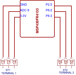
The 3.3 voltage, GND and ADC channel 8 goes through the ST1 screw terminal of the circuit, the GPIO pins P2.5, P8.2 and P8.3 goes through the ST2 screw terminal. The second part of the whole circuit schematics is shown below...


image


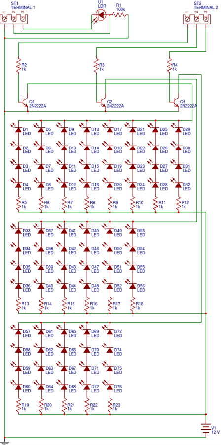
The ST1 screw terminal connected to LDR with 100K resistor, along with voltage divider point, the LDR will act as light sensor and send analog data to MSPFR4133 to the ADC channel 8, the MCU then process the data and send the output in GPIO pins P2.5, P8.2 and P8.3 which connected to ST2 screw terminal. The 3 outputs from MCU are connected to BJT NPN 2N2222A transistors to drive high voltage and control LEDs, as the MCU can able to send not more than 3.3V on GPIO pins. We need to supply secondary voltage which is able to drive high power LEDs, so we can close the 12V secondary voltage circuit by passing Base voltage to each transistor with GPIO outputs. On each Collector side of the transistors the LEDs are connected both in series and parallel, 4 LEDs in series with 1K resistor and the LED series connected in parallel.


Würth Elektronik's high bright LED can drive 3.2V average and 3.6V maximum forward voltage in the typical current rate of 350mA, we can pass maximum limit of 1A current. So in my circuit there is 4 LEDs in series which is 12/4 = 3V for each LED, each series will get 12V of power, so I will get real bright output from WE LEDs... 32 LEDs connected for white light, 24 LEDs connected for yellow light and 20 LEDs for blue light.


I am working on my PCB design for my circuit, I am going to etch it myself and I will post the process...


Würth Elektronik's components are really helping me a lot in my situation, they have sent all the parts I have asked in prompt manner, even they put me in guilty position by asking me "What else you need" I am speechless...This is my personal message to Würth Elektronik - You guys are GREAT and ROCKS image

  • Sign in to reply

Top Comments

  • DAB
    DAB over 9 years ago +1
    Nice start. DAB
  • jc2048
    jc2048 over 9 years ago +1
    Don't do the pcb yet, this isn't going to work. The LEDs won't light up (and the transistors couldn't switch them properly if they did). You need to read up on Ohm's law and look carefully at how diodes…
  • gpolder
    gpolder over 9 years ago in reply to tonyboubady +1
    Hi Antony, why not use the TPS9251 LED driver provided with this roadtest? It will keep the current trough the LEDs constant and you don't have any issues with wasted power heating up resistors. It also…
  • tonyboubady
    tonyboubady over 9 years ago in reply to gpolder

    Hi Gerrit,


    True, I was testing the module TPS9251 and I found it draws only 1A current which I have to cut the LEDs in half the amount...hmmmm I will try my best...

    • Cancel
    • Vote Up 0 Vote Down
    • Sign in to reply
    • More
    • Cancel
  • gpolder
    gpolder over 9 years ago in reply to tonyboubady

    Hi Antony,


    why not use the TPS9251 LED driver provided with this roadtest?

    It will keep the current trough the LEDs constant and you don't have any issues with wasted power heating up resistors.

    It also can be used to switch the LEDs on and off saving you the power transistors.

    image

    • Cancel
    • Vote Up +1 Vote Down
    • Sign in to reply
    • More
    • Cancel
  • tonyboubady
    tonyboubady over 9 years ago in reply to jc2048

    Thank you for your insight Jon... You are absolutely correct...but I am already working on the corrections, I have figured it out the problems...


    The transistor issue...

    I am going to use TIP122 rather than 2N2222A, TIP122 will handle upto 5A of collector current and in maximum peak limit it will handle 8A as per datasheet...I won't go more than 5A, so I am safe on transistor now. The LED sets won't lit up all at once, it will be either white(32 LEDs) or Yellow(24 LEDs) or blue(20 LEDs), not simultaneously... any one of the LED sets will lit up according to sensor data, White LED will draw 2.8A current which will be 2800/8 = 350mA for 32 LEDs, the LEDs are both in series and parallel, the current will split into 8 and stay constant in series for all 4 LEDs, so 350mA for each LEDs for white set. The yellow set will draw 2.1A which will be 2100/6 = 350mA, for blue LED set draws 1.75A which will be 1750/5 = 350mA.


    The voltage in the car...

    I have checked some datasheet about my car's bulb, that my car is using the 55-60watt bulb in 12v, so the Amp will be 60/12=5A, my headlight connected to 5A relay so i don't get more than 5A current for sure...Yes I need to calculate the resistor values and watts in detail as I did resistor values wrong in schematics...and as well the car battery provide enough current to the LEDs as it is 5A and my LED circuit is not more than 2.8A, usually batteries provide needed current to the load, so again I am safe here too, I think... Am I?


    Anything am I missed here...?

    • Cancel
    • Vote Up 0 Vote Down
    • Sign in to reply
    • More
    • Cancel
  • jc2048
    jc2048 over 9 years ago

    Don't do the pcb yet, this isn't going to work.


    The LEDs won't light up (and the transistors couldn't switch them properly if they did).


    You need to read up on Ohm's law and look carefully at how diodes behave.


    Let's start with the transistors and pretend, for the moment, that your LED's were taking their design current of 350mA. The three groups of LEDs would take 1.75A (5 x 350mA), 2.1A (6 x 350mA), and 2.8A (8 x 350mA).

    Absolute maximum for 2N2222A is 800mA, so all three exceed the capability of the transistor by at least twice. So switching them with this transistor is a non-starter.


    Even if the current were much less, it wouldn't work as you expect. Let's say that there were just two strings of LEDs taking 2 x 350mA = 700mA. If you look at the datasheet for the transistor it says that the current gain falls to 40 at 500mA collector current. Let's pretend that it's the same for 700mA (not true, but good enough for this discussion), then you need 700mA/40 base current which is 17.5mA. But your base resistor only gives you about (5V-0.6V)/1000 ohms = 4.4mA (I'm assuming the uP IO is 5V, adjust accordingly if it's 3.3V), which isn't enough. You could decrease the size of the resistor, but then you'd be sourcing 18mA from your IO pin which it would manage but is a bit on the high side.


    Anyway, to get around this you either need more gain and a heftier part (look at a darlington pair) or use an n-channel MOSFET.


    Now to the LEDs.


    Imagine the LEDs weren't there and were replaced with wire links. What is the resistor current? By Ohm's law, it's 12V/1000 ohms = 12mA. Let's put back one LED with a voltage drop of 3.2V. What's the current now? (12V - 3.2V)/1000 = 8.8mA. [That value isn't accurate - the forward voltage is at the rated current of 350mA and would be a good bit less for only 8mA - but the point is that the 12mA is the most you can ever get and adding diodes reduces from that.]


    So, let's say we put three diodes in a string, run them from the 12V, and calculate the resistor value we need.


    The resistor value to get 350mA is (12V - (3 x 3.2v))/0.35A = 6.85 ohms. The resistor heat dissipation is 2.4V x 0.35 A = 0.84W, so that would need to be a 1W resistor. [Note, while we're here, that each LED is about 1W, so the resistor is using about a quarter of the total power for the string, which is quite wasteful.]


    However, the LED will warm up (how much depends on how good your heatsinking is) and the forward voltage will drop. That means more voltage across the resistor and the current will go up. A drop of 0.2v [for each LED] isn't unreasonable for the kind of heatsinking you'll manage (LED chip at 80C rather than the 25C at which the datasheet Vf value is measured). That would then give a current of (12 - (3 x 3.0))/6.85 = 438mA. So, you can see the resistor isn't regulating the current very well at all. It's also worth bearing in mind that the forward voltage is just a typical figure, and the actual LEDs you have may be different.


    You also have the further problem that your supply isn't really 12V in a car (automobile). If the alternator is running, the regulator will hold the supply higher than that to charge the battery, and if it isn't running the supply depends on how run down the battery is. [Be aware,too, that you need good protection on automotive circuits - there can be hugh spikes on the supply.]


    If you use an IC LED driver, it will measure the current through the LEDs and keep adjusting the voltage across the LEDs to keep that current at the required value. Any changes, because the LEDs differ from the typical value, or because they heat up, or because the supply voltage varies, don't matter [as long as they're within the range the driver can adjust for, obviously].

    • Cancel
    • Vote Up +1 Vote Down
    • Sign in to reply
    • More
    • Cancel
  • tonyboubady
    tonyboubady over 9 years ago in reply to DAB

    Thanks... hope it will be a nice finish too image

    • Cancel
    • Vote Up 0 Vote Down
    • Sign in to reply
    • More
    • Cancel
>
element14 Community

element14 is the first online community specifically for engineers. Connect with your peers and get expert answers to your questions.

  • Members
  • Learn
  • Technologies
  • Challenges & Projects
  • Products
  • Store
  • About Us
  • Feedback & Support
  • FAQs
  • Terms of Use
  • Privacy Policy
  • Legal and Copyright Notices
  • Sitemap
  • Cookies

An Avnet Company © 2025 Premier Farnell Limited. All Rights Reserved.

Premier Farnell Ltd, registered in England and Wales (no 00876412), registered office: Farnell House, Forge Lane, Leeds LS12 2NE.

ICP 备案号 10220084.

Follow element14

  • X
  • Facebook
  • linkedin
  • YouTube