element14 Community
element14 Community
    Register Log In
  • Site
  • Search
  • Log In Register
  • Community Hub
    Community Hub
    • What's New on element14
    • Feedback and Support
    • Benefits of Membership
    • Personal Blogs
    • Members Area
    • Achievement Levels
  • Learn
    Learn
    • Ask an Expert
    • eBooks
    • element14 presents
    • Learning Center
    • Tech Spotlight
    • STEM Academy
    • Webinars, Training and Events
    • Learning Groups
  • Technologies
    Technologies
    • 3D Printing
    • FPGA
    • Industrial Automation
    • Internet of Things
    • Power & Energy
    • Sensors
    • Technology Groups
  • Challenges & Projects
    Challenges & Projects
    • Design Challenges
    • element14 presents Projects
    • Project14
    • Arduino Projects
    • Raspberry Pi Projects
    • Project Groups
  • Products
    Products
    • Arduino
    • Avnet Boards Community
    • Dev Tools
    • Manufacturers
    • Multicomp Pro
    • Product Groups
    • Raspberry Pi
    • RoadTests & Reviews
  • Store
    Store
    • Visit Your Store
    • Choose another store...
      • Europe
      •  Austria (German)
      •  Belgium (Dutch, French)
      •  Bulgaria (Bulgarian)
      •  Czech Republic (Czech)
      •  Denmark (Danish)
      •  Estonia (Estonian)
      •  Finland (Finnish)
      •  France (French)
      •  Germany (German)
      •  Hungary (Hungarian)
      •  Ireland
      •  Israel
      •  Italy (Italian)
      •  Latvia (Latvian)
      •  
      •  Lithuania (Lithuanian)
      •  Netherlands (Dutch)
      •  Norway (Norwegian)
      •  Poland (Polish)
      •  Portugal (Portuguese)
      •  Romania (Romanian)
      •  Russia (Russian)
      •  Slovakia (Slovak)
      •  Slovenia (Slovenian)
      •  Spain (Spanish)
      •  Sweden (Swedish)
      •  Switzerland(German, French)
      •  Turkey (Turkish)
      •  United Kingdom
      • Asia Pacific
      •  Australia
      •  China
      •  Hong Kong
      •  India
      •  Korea (Korean)
      •  Malaysia
      •  New Zealand
      •  Philippines
      •  Singapore
      •  Taiwan
      •  Thailand (Thai)
      • Americas
      •  Brazil (Portuguese)
      •  Canada
      •  Mexico (Spanish)
      •  United States
      Can't find the country/region you're looking for? Visit our export site or find a local distributor.
  • Translate
  • Profile
  • Settings
RoadTests & Reviews
  • Products
  • More
RoadTests & Reviews
Blog TI SWIFT™︎ Power Module EVM Review: Part 3 Analog tests of the Power Module
  • Blog
  • RoadTest Forum
  • Documents
  • RoadTests
  • Reviews
  • Polls
  • Files
  • Members
  • Mentions
  • Sub-Groups
  • Tags
  • More
  • Cancel
  • New
Join RoadTests & Reviews to participate - click to join for free!
  • Share
  • More
  • Cancel
  • Author Author: snidhi
  • Date Created: 2 Apr 2018 11:26 AM Date Created
  • Views 2125 views
  • Likes 3 likes
  • Comments 19 comments
Related
Recommended
  • low noise regulator
  • high-current
  • dcdc converters
  • dcdc buck regulator
  • switching frequency
  • power efficiency

TI SWIFT™︎ Power Module EVM Review: Part 3 Analog tests of the Power Module

snidhi
snidhi
2 Apr 2018

Part 2: Test the analog features of the TPSM84A21 EVM


To be Tested Features of TPSM84A21:

  1. Output voltage ripple measurements (with and without external capacitors)
  2. Tests at high output current with external load
  3. The Vin, Vout and PGOOD start up waveforms
  4. The Vin, Vout and PGOOD shutdown waveforms


Features of TPSM84A21 IC:

  1. Ultra-Fast Load Step Response
  2. Efficiencies up to 88%
  3. 1% Output Voltage Accuracy
  4. 4 MHz Switching Frequency
  5. Synchronizes to an External Clock
  6. Power Good Output
  7. Pre-Bias Output Start-Up
  8. Programmable Under-Voltage Lockout (UVLO)


Output voltage ripple measurements (without external capacitors)


Using the reference below Understanding, Measuring, and Reducing Output Voltage Ripple

Probe Sensitivity – Using 10X vs 1X Probes: When trying to measure signals in the sub ~10mV range, using a 10x probe is not appropriate. The sensitivity of the probe is not high enough to have a clean signal reading. A simple 1x probe should be used for measurements under 10mV.


Measurement Conditions in the oscilloscope:  1x probe settings, Noise Reject ON, LPF ON, No o/p load, BW limit set 20MHz, MEMDepth 70Mpoints, AC Coupling, 1Mohm input impedance. Ch1: Vin Yellow Ch2: Vout Blue, Measurement cable from the EVM to the scope is a RF cable 1x with BNC.


The Vout ripple is also load dependent but here the measurements where done without external load


image

Data-sheet Preview

image

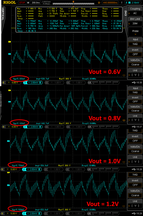
Without Filtering Capacitors at the input and output For Vin = 7.969V

image

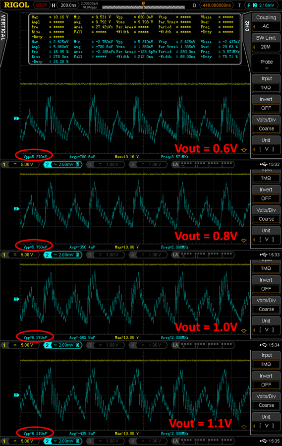
Without Filtering Capacitors at the input and output For Vin = 10V

image

Without Filtering Capacitors at the input and output For Vin = 14V


One can conclude from these results that there is a slow rise in the output ripple from 5 mVpp to 8mVpp. But still it is low in comparison to other fast switching DC/DC converter.


Output voltage ripple measurements (with external capacitors)


Measurement Conditions in the oscilloscope: Noise Reject ON, LPF ON, No o/p load, BW limit set 20MHz, MEMDepth 70Mpoints, AC Coupling, 1Mohm input impedance. Ch1: Vout Yellow After filtering capacitors  Ch2: Vout Blue measured before filtering capacitors.


image


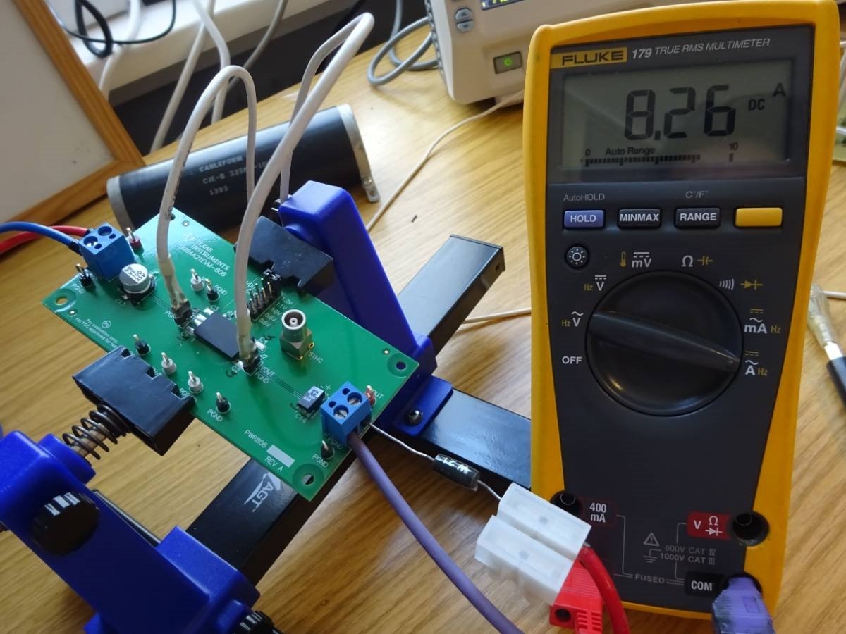
Tests at High output current with external load: Very short cables were use to connect from Rload to the DMM.

The measurements were also verified using shunt resistance of 0.01 ohm at the oscilloscope.


image


VinVout Measured

RLoad

cement Resistor +

Burden resistance of Fluke 179

Output Load current

calculated

Output Load current

Measured

@8V,10V,14V1.2V0.5ohm +0.037ohm = 0.537 ohm2.234 Amp2.263 Amp
@8V,10V,14V1.1V0.5ohm +0.037ohm = 0.537 ohm2.0484 Amp2.055 Amp
@8V,10V,14V1V0.5ohm +0.037ohm = 0.537 ohm1.862 Amp1.891 Amp
@8V,10V,14V0.8V0.5ohm +0.037ohm = 0.537 ohm1.489 Amp1.502 Amp
@8V,10V,14V0.6V0.5ohm +0.037ohm = 0.537 ohm1.1173 Amp1.128 Amp
@8V,10V,14V0.500V0.5ohm +0.037ohm = 0.537 ohm0.9310 Amp0.955 Amp


The device closely delivers the required output current although one can see a decline as the current requirement increases. The measured output current remains stable for Vin voltages from 8V to 14V.


Rload = 0.1 Ohm

image


Vin

Vout +

Burden voltage 37mV/A

RLoad

21W Resistor + 0.037ohm

Output Load current

calculated

Output Load current

Measured

@8V,10V,14V1.2V0.1 ohm + 0.037 ohm = 0.137ohm
8.759 Amp8.351 Amp
@8V,10V,14V1.1V0.1 ohm + 0.037 ohm = 0.137ohm8.029 Amp7.61 Amp
@8V,10V,14V1.0V0.1 ohm + 0.037 ohm = 0.137ohm7.299 Amp7.1 Amp
@8V,10V,14V0.8V0.1 ohm + 0.037 ohm = 0.137ohm5.8394 Amp5.584 Amp
@8V,10V,14V0.6V0.1 ohm + 0.037 ohm = 0.137ohm4.379 Amp4.211 Amp
@8V,10V,14V0.5V0.1 ohm + 0.037 ohm = 0.137ohm3.649 Amp3.565 Amp


In both the tests, the resistor became very hot very quickly. I had to turn off the setup after sometime to avoid any melting situation. Even with the 21Watt 0.1 ohm the device turns quite hot. At high current and for low Vout the efficiency of the converter is as mentioned in the datasheet. The measured output current remains very stable for Vin voltages from 8V to 14V.


Another important conclusion can be derived here that the difference between the calculated load current and actual measured load current also increases drastically to around 300 mA when loads start drawing current higher than 7.5Amp.

Although the deviation of  Measured current@load from Calculated current value@load for 1Amp to 7Amp was only in the order of 20mA which can be understood as drawn by additional cable resistance.


The Vin, Vout and PGOOD Start up waveforms

Setup: Vin = 10V, Vout = 500mv Iout = 1A, Rload = 0.5ohm

image

The Vin and Vout rise times are comparable to those in the datahseet. Vin@6ms; Vout@4ms; PGood has a steep slope. One can see here that the PGOOD signal in ON only when the Vout reaches its stable output voltage~99%. Whereas Vout start rising when reached around 7V. And Vout has a faster rise time.


The Vin, Vout and PGOOD shutdown waveforms

Setup: Vin = 10V, Vout = 500mv Iout = 1A, Rload = 0.5ohm

image

The shutdown waveforms were rather difficult to catch as they should be measured in the 200ms/div window and not in 200us/div(as in the datasheet)

Vout and Pgood have a sharp falling edge but the Vin signal takes around 2 sec to fully get to the base level.


Short Conclusion: The TPSM84A21 is good device with fast output rising voltages. It is able to drive higher currents consistently even with as low as 8Vin and 1.2Vout without any issues. But it falls short in achieving a higher efficiency at high load currents at low input voltage. The voltage output ripple is well under control (less than 20mV) even in high current range which is pretty good. 


References:

Power Tips: Measuring Vout Ripple in DC/DC Converters

Power Tips: Simply estimate load transient response

Understanding, Measuring, and Reducing Output Voltage Ripple

Line and Load Transient Testing for Power Supplies


TI SWIFTTm Power Module EVM Review: Part 2 Test Setup Description

TI SWIFTTmPower Module EVM Review:  Part 4 Dynamically adjust the output voltage using external DAC

Go Back To: Road Test Review of TPSM84A21 Power Module

  • Sign in to reply

Top Comments

  • hlipka
    hlipka over 7 years ago in reply to fmilburn +2
    The measured effect here is that the multimeter used for current measurement has a burden voltage due to its internal shunt. For the Fluke 179, this is (in the 10A range) 37mV/A - that is, 370mV for 10A…
  • snidhi
    snidhi over 7 years ago in reply to fmilburn

    fmilburn Yes, I think the resistance will change due to heating and also change dynamically. But I did not check it exactly with a thermal camera. And the problem is that we are dealing with resistance in the range of 0.1 to 0.01 milliohm as load which is very fragile lets say. Any additional resistance or device in series or parallel immediately impacts the total load resistance.


    Although I have tried to minimize cables and use only RF well insulated cable to BNC in 1x mode as I do not want to add additional probe resistance or GND lead wire.

    I want to do upto 15Amp measurements but I need a good load for it.


    Although its mentioned in the data-sheet that max power dissipation is less than 3W@ 10A. So yes maybe less wattage resistors as load will work here.

    • Cancel
    • Vote Up 0 Vote Down
    • Sign in to reply
    • More
    • Cancel
  • snidhi
    snidhi over 7 years ago in reply to hlipka

    Yes I know they are different. But to minimize noise from the air or from antennas needs a well insulated box called or TEM Cell which was not the aim of this experiment.


    2.0 Ripple and Noise


    The ripple exists because, during a portion of the converter’s operating cycle, energy is transferred to the secondary from the primary and the output voltage increases slightly. During the time interval when there is no energy transfer to the secondary, the load current is supplied by stored energy in the output capacitance and inductance of the converter, and the output voltage decreases slightly as this energy is depleted.


    Ripple is a low frequency component and will be occur at the same as the converter operating frequency, or some multiple thereof. Noise is much more variable and harder to predict than ripple. It is caused by ringing in parasitic inductances due to the large values of di/dt that occur internally in a switching converter. The noise is much higher frequency than the ripple and can be up into the MHz range. Noise occurs in the form of “bursts” at the time of switching activity in the converter, so therefore appears to be superimposed upon the peaks and valleys of the ripple waveform as shown in Fig 1.


    3.1 Limit the bandwidth on the measurement: Output Ripple and Noise is usually specified with a 20MHz Bandwidth. This reduces the high frequency noise components. The majority of scopes will have this available internally.


    Reference: https://www.digikey.de/Web%20Export/Supplier%20Content/Excelsys_633/PDF/excelsys-measuring-ripple-noise.pdf

    • Cancel
    • Vote Up 0 Vote Down
    • Sign in to reply
    • More
    • Cancel
  • hlipka
    hlipka over 7 years ago in reply to snidhi

    For ripple: yes. For noise: no.

    • Cancel
    • Vote Up 0 Vote Down
    • Sign in to reply
    • More
    • Cancel
  • snidhi
    snidhi over 7 years ago in reply to hlipka

    Please look in the datasheet the recommended method to do the ripple measurement is with 20MHZ BW and the integrated caps


    Link: http://www.ti.com/lit/ds/symlink/tpsm84a21.pdf


    image

    • Cancel
    • Vote Up 0 Vote Down
    • Sign in to reply
    • More
    • Cancel
  • snidhi
    snidhi over 7 years ago in reply to snidhi

    Sorry for the previous weird font post. The page is behaving crazy


    Cheers

    • Cancel
    • Vote Up 0 Vote Down
    • Sign in to reply
    • More
    • Cancel
>
element14 Community

element14 is the first online community specifically for engineers. Connect with your peers and get expert answers to your questions.

  • Members
  • Learn
  • Technologies
  • Challenges & Projects
  • Products
  • Store
  • About Us
  • Feedback & Support
  • FAQs
  • Terms of Use
  • Privacy Policy
  • Legal and Copyright Notices
  • Sitemap
  • Cookies

An Avnet Company © 2025 Premier Farnell Limited. All Rights Reserved.

Premier Farnell Ltd, registered in England and Wales (no 00876412), registered office: Farnell House, Forge Lane, Leeds LS12 2NE.

ICP 备案号 10220084.

Follow element14

  • X
  • Facebook
  • linkedin
  • YouTube