element14 Community
element14 Community
    Register Log In
  • Site
  • Search
  • Log In Register
  • Community Hub
    Community Hub
    • What's New on element14
    • Feedback and Support
    • Benefits of Membership
    • Personal Blogs
    • Members Area
    • Achievement Levels
  • Learn
    Learn
    • Ask an Expert
    • eBooks
    • element14 presents
    • Learning Center
    • Tech Spotlight
    • STEM Academy
    • Webinars, Training and Events
    • Learning Groups
  • Technologies
    Technologies
    • 3D Printing
    • FPGA
    • Industrial Automation
    • Internet of Things
    • Power & Energy
    • Sensors
    • Technology Groups
  • Challenges & Projects
    Challenges & Projects
    • Design Challenges
    • element14 presents Projects
    • Project14
    • Arduino Projects
    • Raspberry Pi Projects
    • Project Groups
  • Products
    Products
    • Arduino
    • Avnet & Tria Boards Community
    • Dev Tools
    • Manufacturers
    • Multicomp Pro
    • Product Groups
    • Raspberry Pi
    • RoadTests & Reviews
  • About Us
  • Store
    Store
    • Visit Your Store
    • Choose another store...
      • Europe
      •  Austria (German)
      •  Belgium (Dutch, French)
      •  Bulgaria (Bulgarian)
      •  Czech Republic (Czech)
      •  Denmark (Danish)
      •  Estonia (Estonian)
      •  Finland (Finnish)
      •  France (French)
      •  Germany (German)
      •  Hungary (Hungarian)
      •  Ireland
      •  Israel
      •  Italy (Italian)
      •  Latvia (Latvian)
      •  
      •  Lithuania (Lithuanian)
      •  Netherlands (Dutch)
      •  Norway (Norwegian)
      •  Poland (Polish)
      •  Portugal (Portuguese)
      •  Romania (Romanian)
      •  Russia (Russian)
      •  Slovakia (Slovak)
      •  Slovenia (Slovenian)
      •  Spain (Spanish)
      •  Sweden (Swedish)
      •  Switzerland(German, French)
      •  Turkey (Turkish)
      •  United Kingdom
      • Asia Pacific
      •  Australia
      •  China
      •  Hong Kong
      •  India
      • Japan
      •  Korea (Korean)
      •  Malaysia
      •  New Zealand
      •  Philippines
      •  Singapore
      •  Taiwan
      •  Thailand (Thai)
      • Vietnam
      • Americas
      •  Brazil (Portuguese)
      •  Canada
      •  Mexico (Spanish)
      •  United States
      Can't find the country/region you're looking for? Visit our export site or find a local distributor.
  • Translate
  • Profile
  • Settings
RoadTests & Reviews
  • Products
  • More
RoadTests & Reviews
Review Blogs Zero Gecko follow up: talking to a microSD card via SPI
  • Blogs
  • RoadTest Forum
  • Documents
  • RoadTests
  • Reviews
  • Polls
  • Files
  • Members
  • Sub-Groups
  • More
  • Cancel
  • New
Join RoadTests & Reviews to participate - click to join for free!
  • Share
  • More
  • Cancel
  • Author Author: Jan Cumps
  • Date Created: 17 Nov 2014 8:29 PM Date Created
  • Views 4188 views
  • Likes 8 likes
  • Comments 12 comments
Related
Recommended
  • RoadTest
  • microsd
  • spi
  • zero_gecko_starter_kit
  • feature_tutorial
  • zero_gecko

Zero Gecko follow up: talking to a microSD card via SPI

Jan Cumps
Jan Cumps
17 Nov 2014

After I finished my RoadTest review of the Zero Gecko starter kit, I still had some functionality that I want to try out. One of them is SPI support.

image

I have an SD card breakout board in my toolbox. That's what I'm connecting to the starter kit.

Simplicity Studio comes with an application note that explains interfacing Gecko to SD Cards. That AN0030 comes with an example for several kits, but not for the Zero Gecko.

I'm porting that example to my starter kit.


My first naive attempt was to start from the application note and try to change that to the Zero Gecko. I haven't succeeded to create a source case that compiles from that exercise.

So I decided to take a different approach. I Created a new project based on the ZG Blinky example. I knew that one compiles without issues image.


Then I morphed that into a working SPI example by taking the Serial Peripheral Interface (SPI) Example from eewiki.net.


Video:


You don't have permission to edit metadata of this video.
Edit media
x
image
Upload Preview
image


Getting that example to compile was not that difficult. This is the code:

#include "em_device.h"
#include "em_system.h"
#include "em_chip.h"
#include "em_cmu.h"
#include "em_gpio.h"
#include "em_usart.h"


#define SPI_PORTD    gpioPortD // USART1 (location #3) MISO and MOSI are on PORTD
#define SPI_PORTC    gpioPortC // USART1 (location #3) SS and SCLK are on PORTC
#define SPI_MISO_PIN  6  // PD6
#define SPI_MOSI_PIN  7  // PD7
#define SPI_CS_PIN    14 // PC14
#define SPI_SCLK_PIN  15 // PC15
#define SPI_nHLD_PIN  13 // PC13
#define SPI_nWP_PIN  11 // PC11


#define RX_BUFFER_SIZE 2


/* SPI functions */
void CS_pin_clr(void);
void CS_pin_set(void);


/* Global variables */
uint8_t rx_buffer[RX_BUFFER_SIZE];


int main () {


  CHIP_Init();
  uint16_t i;


  // Clear software buffer (optional)
  for(i=0; i<RX_BUFFER_SIZE; i++) {
    rx_buffer[i] = 0;
  }


  /* Setup clock tree */
  /* Use 24MHz crystal as HF system clock source */
  /* Run Low Energy Peripheral B system as a high speed peripheral (use CORECLCK/2 as source) */
  CMU_OscillatorEnable(cmuOsc_HFXO, true, true);          // enable XTAL osc and wait for it to stabilize
  CMU_ClockSelectSet(cmuClock_HF, cmuSelect_HFXO);        // select HF XTAL osc as system clock source (24MHz)
  if(cmuSelect_HFRCO != CMU_ClockSelectGet(cmuClock_HF)) { // make sure HFRCO is no longer the selected clock source
    CMU_OscillatorEnable(cmuOsc_HFRCO, false, false);      // disable HFRCO to save power
  }
  CMU_ClockSelectSet(cmuClock_LFB, cmuSelect_CORELEDIV2);  // select HFCORECLK/2 as clock source to LFB
  CMU_ClockEnable(cmuClock_CORELE, true);                  // enable the Low Energy Peripheral Interface clock


  CMU_ClockEnable(cmuClock_GPIO, true);                    // enable GPIO peripheral clock
  CMU_ClockEnable(cmuClock_USART1, true);                  // enable USART1 peripheral clock


  /* Configure GPIO */
  GPIO_PinModeSet(SPI_PORTD, SPI_MISO_PIN, gpioModeInput, 0);      // configure MISO pin as input, no filter
  GPIO_PinModeSet(SPI_PORTD, SPI_MOSI_PIN, gpioModePushPull, 1);    // configure MOSI pin as output, initialize high
  GPIO_PinModeSet(SPI_PORTC, SPI_CS_PIN, gpioModePushPull, 1);      // configure CS pin as output, initialize high
  GPIO_PinModeSet(SPI_PORTC, SPI_SCLK_PIN, gpioModePushPull, 0);    // configure SCLK pin as output, initialize low
  GPIO_PinModeSet(SPI_PORTC, SPI_nHLD_PIN, gpioModePushPull, 1);    // configure nHLD pin as output, initialize high
  GPIO_PinModeSet(SPI_PORTC, SPI_nWP_PIN, gpioModePushPull, 0);    // configure nWP pin as output, initialize low


  /* Configure SPI Port (USART1 in sync mode) */
  USART_InitSync_TypeDef spi_init = {
    .enable = usartEnable,        // enable bidirectional data (TX and RX)
    .refFreq = 0,                // measure source clock
    .baudrate = 12000000,        // 12Mbps is max data rate with 24MHz clock source
    .databits = usartDatabits8,  // 8 data bits per frame
    .master = true,              // configure as SPI master
    .msbf = true,                // transmit msb first (requirement of W25X40CL)
    .clockMode = usartClockMode0, // clock idles low, data setup on rising edge, sampled on falling edge
  };
  USART_IntClear(USART1, 0x1FF9);                // clear interrupt flags (optional)
  USART_InitSync(USART1, &spi_init);              // apply configuration to USART1
  USART1->ROUTE = (3 << 8) | ( 1 << 3)| (3 << 0); // use location #3, enable TX/RX/CLK pins


  /* Get Device ID from SPI Slave (see W25X40CL datasheet for details) */
  CS_pin_clr();                                    // select slave device


  rx_buffer[0] = USART_SpiTransfer(USART1, 0x90);  // send 'Device ID' command and clear RX buffer
  for(i=0; i<3; i++) {
    rx_buffer[0] = USART_SpiTransfer(USART1, 0x00); // send 3 '00' bytes
  }
  rx_buffer[0] = USART_SpiTransfer(USART1, 0xFF);  // send dummy byte '0xFF' to receive manuf. id
  rx_buffer[1] = USART_SpiTransfer(USART1, 0xFF);  // send dummy byte '0xFF' to receive device id


  CS_pin_set();                                    // deselect slave device


  while(1);
}


// This function drives the CS pin low
void CS_pin_clr(void) {
  GPIO_PinOutClear(SPI_PORTC, SPI_CS_PIN);
}


// This function drives the CS pin high
void CS_pin_set(void) {
  GPIO_PinOutSet(SPI_PORTC, SPI_CS_PIN);
}


I was pleasantly surprised that this simple trick already resulted in a 2-way communication with the SD Card:


image

Then I moved the SILabs AN0030 main file's code over to that example, and worked on getting the right pins addressed.

Step by step I removed non-applicable code, added header and include files, made small mods, resolving one build error after the other.

The code that I removed was related to development kit specific (BSP) calls. The remaining tasks were to find additional .c and .h files in the Simplicity Studio install folders and add them to the project.

The toughest one to resolve was a 'region RAM overflowed with stack' error. There was a solution documented for the Tiny Gecko on the SILabs forum. This solution works for the Zero Gecko too.

I had to alter line 17 in the ffconf.h file in the reptile/fatfs/inc folder:


#define
_FS_TINY 1 /* 0:Normal or 1:Tiny */


/* When _FS_TINY is set to 1, FatFs uses the sector buffer in the file system
/  object instead of the sector buffer in the individual file object for file
/  data transfer. This reduces memory consumption 512 bytes each file object. */


All is well that end well. My example compiles and I have successful communication with the SD card. Here's the capture of the SPI communication:


image

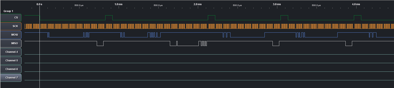
and the SPI protocal analysis:

image


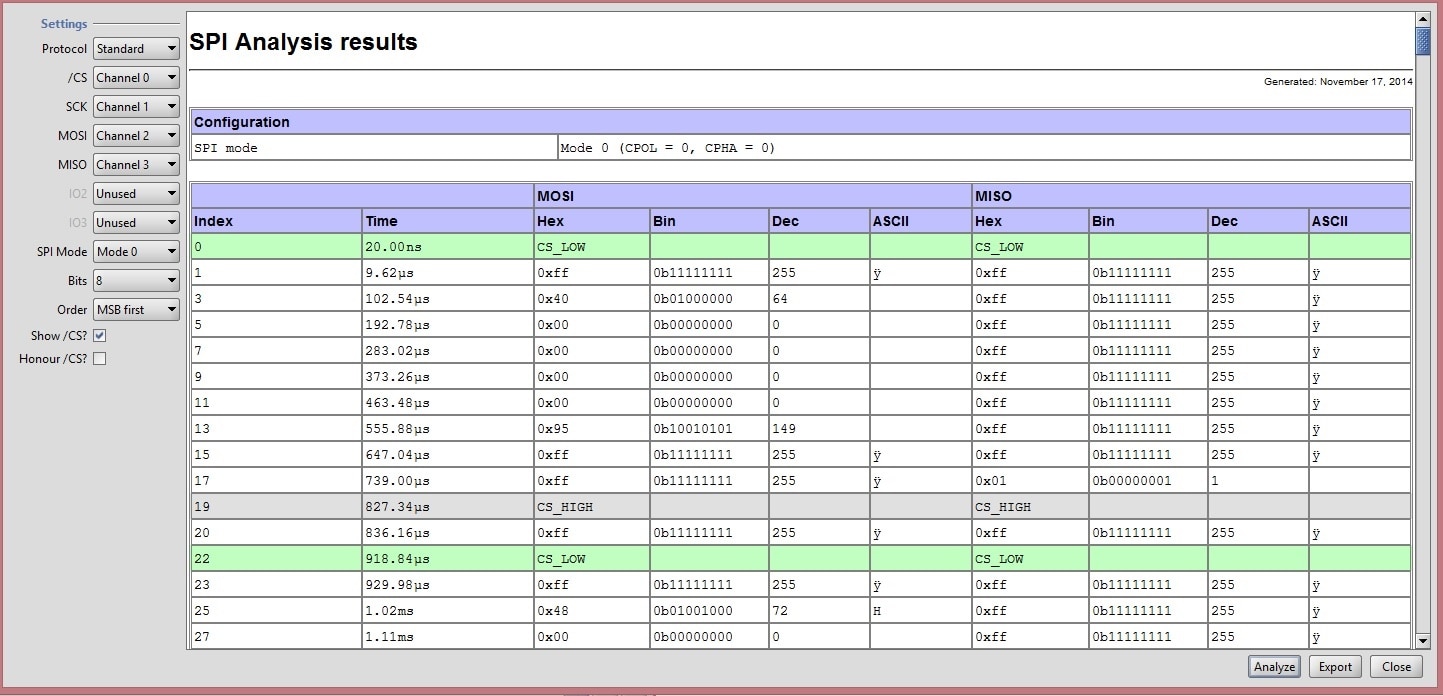
The project is available in the archive attached to this post.


Additional info


Hardware

I received the EFM32Tm Zero Gecko Starter Kit w/ Sensor Card as part of the element14 RoadTest.

The SD Card  breakout board is from LC Studio. I used an unbranded 4 GB micro SD card.

image


image


imageimage


Logic Analyzer

I use the Gadget Factory Papilio Pro FPGA board as logic analyzer hardware. I made my own IO buffer based on their 16-bitIOBufferWing.

The firmware (or whatever that is called on an FPGA image ) is work from Magnus, that I have slightly adapted. It's available from Porting Logic Analyser from One to Pro - Page 3 - Papilio Pro - Gadget Factory Forum .

The logic analyzer client software is available on OLS - alternative Java client .


Read more about this on Make a Logic Analyzer from your Dev Kit Part 2: Papilio FPGA


image

Attachments:
STK3200_sd_card.zip
  • Sign in to reply

Top Comments

  • baldengineer
    baldengineer over 11 years ago in reply to Jan Cumps +2
    Thanks Jan, I am still not sure what I did wrong, so I started over from scratch. Your code example now compiles. Notes for others: 1. If you've loaded this code previously, it isn't enough to close or…
  • withboobs
    withboobs over 8 years ago +2
    Please check my post at https://github.com/OneBoobLess/zerogecko-stk3200-datalogger Board: Silicon Labs EFM32ZG-STK3200 Development Kit Device: EFM32ZG222F32 Digital clock with Real Time Clock DS3231 …
  • baldengineer
    baldengineer over 11 years ago +1
    Nice work, seems strange that SPI and FAT wasn't included with a kit that begs to be a datalogger. I'm trying to follow your work but running into many problems. I've downloaded the ZIP file you attached…
  • geralds
    geralds over 8 years ago in reply to Jan Cumps

    Thank you very much!

    Yes i know - it will be my own risk. image image

    • Cancel
    • Vote Up 0 Vote Down
    • Sign in to reply
    • More
    • Cancel
  • Jan Cumps
    Jan Cumps over 8 years ago in reply to geralds

    Thanks for the heads-up, Gerald. I'll fix that.

    All my published code is free to use - no restrictions and no guarantees image.

    • Cancel
    • Vote Up 0 Vote Down
    • Sign in to reply
    • More
    • Cancel
  • geralds
    geralds over 8 years ago in reply to Jan Cumps

    The toughest one to resolve was a 'region RAM overflowed with stack' error. There was a solution documented for the Tiny Gecko on the SILabs forum. This solution works for the Zero Gecko too.

    Hi Jan,


    in your road test review there i found a small mistake - the link to silabs have two "http//".

    Solved: How to use library/header files from example proje... - Silicon Labs Community


    Thanks a lot for the fine review.

    Is it allowed to use some code fragments and circuit diagram parts for my projects?


    Best Regards

    Gerald

    ---

    • Cancel
    • Vote Up 0 Vote Down
    • Sign in to reply
    • More
    • Cancel
  • withboobs
    withboobs over 8 years ago

    Please check my post at

    https://github.com/OneBoobLess/zerogecko-stk3200-datalogger


    Board: Silicon Labs EFM32ZG-STK3200 Development Kit Device: EFM32ZG222F32


    Digital clock with Real Time Clock DS3231 (I2C), Rel. Humidity and Temperature Sensor Si7021 (I2C), and SD Card (SPI) with Memory LCD (SPI) on the EFM32ZG-STK3200.


    This is extension of the work by Jan Cumps, from 2014, posted at https://www.element14.com/community/groups/roadtest/blog/2014/11/17/zero-gecko-follow-up-talking-to-a-microsd-card-via-spi which allows data logging through SD Card to EFM32 Zero Gecko STK3200.


    In the present project, the digital clock (example project for EFM32ZG) is combined with the environmental monitor (temperature and relative humidity), where all data is displayed on the LCD screen. In addition, the data can be saved to the SD card, if user chooses so.

    Challenge of the project was how to share SPI bus between the display and the SD Card, and how to reuse memory used by the Graphical LIBrary (GLIB) considering that the two libraries combined require more memory then what EMF32ZG has (4kB RAM), see discussion initiated by WithBoobs at http://community.silabs.com/t5/32-bit-MCU/ZeroGecko-with-SDK3200-How-to-add-SPI-SD-card-to-the-GLIB-ef/td-p/189292


    This being said, the datalogger is operated as follows: 1. The user can start/stop data recording by pressing PB1 button. 2. The user can set time, and date, and write it to DS3231. PB0 button is used to select what to change, while the Capsense buttons are used to increase/decrease current value. Cycling PB0 makes a bar be drawn under a time/date setting that can be changed. Continue cycling PB0 until the bar is no longer visible makes device accepts new values and store them in DS3231.

    Also, for this project the original 16x20 numbers-only font was expanded with few characters ('C', '.' and '%') so that temperature and relative humidity can be printed in the same size as the time digits with their units.

    Lastly, this project combines all files for the SimplicityStudio v.4.4 and later, minus the system specific files.

    Author: OneBoobLess, 2017

    • Cancel
    • Vote Up +2 Vote Down
    • Sign in to reply
    • More
    • Cancel
  • Jan Cumps
    Jan Cumps over 11 years ago

    Attempt to combine the weather station example and this SD card port into one project: EFM32Tm Zero Gecko Starter Kit w/ Sensor Card: logging to SD card

    • Cancel
    • Vote Up +1 Vote Down
    • Sign in to reply
    • More
    • Cancel
>
element14 Community

element14 is the first online community specifically for engineers. Connect with your peers and get expert answers to your questions.

  • Members
  • Learn
  • Technologies
  • Challenges & Projects
  • Products
  • Store
  • About Us
  • Feedback & Support
  • FAQs
  • Terms of Use
  • Privacy Policy
  • Legal and Copyright Notices
  • Sitemap
  • Cookies

An Avnet Company © 2025 Premier Farnell Limited. All Rights Reserved.

Premier Farnell Ltd, registered in England and Wales (no 00876412), registered office: Farnell House, Forge Lane, Leeds LS12 2NE.

ICP 备案号 10220084.

Follow element14

  • X
  • Facebook
  • linkedin
  • YouTube