element14 Community
element14 Community
    Register Log In
  • Site
  • Search
  • Log In Register
  • Community Hub
    Community Hub
    • What's New on element14
    • Feedback and Support
    • Benefits of Membership
    • Personal Blogs
    • Members Area
    • Achievement Levels
  • Learn
    Learn
    • Ask an Expert
    • eBooks
    • element14 presents
    • Learning Center
    • Tech Spotlight
    • STEM Academy
    • Webinars, Training and Events
    • Learning Groups
  • Technologies
    Technologies
    • 3D Printing
    • FPGA
    • Industrial Automation
    • Internet of Things
    • Power & Energy
    • Sensors
    • Technology Groups
  • Challenges & Projects
    Challenges & Projects
    • Design Challenges
    • element14 presents Projects
    • Project14
    • Arduino Projects
    • Raspberry Pi Projects
    • Project Groups
  • Products
    Products
    • Arduino
    • Avnet Boards Community
    • Dev Tools
    • Manufacturers
    • Multicomp Pro
    • Product Groups
    • Raspberry Pi
    • RoadTests & Reviews
  • About Us
  • Store
    Store
    • Visit Your Store
    • Choose another store...
      • Europe
      •  Austria (German)
      •  Belgium (Dutch, French)
      •  Bulgaria (Bulgarian)
      •  Czech Republic (Czech)
      •  Denmark (Danish)
      •  Estonia (Estonian)
      •  Finland (Finnish)
      •  France (French)
      •  Germany (German)
      •  Hungary (Hungarian)
      •  Ireland
      •  Israel
      •  Italy (Italian)
      •  Latvia (Latvian)
      •  
      •  Lithuania (Lithuanian)
      •  Netherlands (Dutch)
      •  Norway (Norwegian)
      •  Poland (Polish)
      •  Portugal (Portuguese)
      •  Romania (Romanian)
      •  Russia (Russian)
      •  Slovakia (Slovak)
      •  Slovenia (Slovenian)
      •  Spain (Spanish)
      •  Sweden (Swedish)
      •  Switzerland(German, French)
      •  Turkey (Turkish)
      •  United Kingdom
      • Asia Pacific
      •  Australia
      •  China
      •  Hong Kong
      •  India
      •  Korea (Korean)
      •  Malaysia
      •  New Zealand
      •  Philippines
      •  Singapore
      •  Taiwan
      •  Thailand (Thai)
      • Americas
      •  Brazil (Portuguese)
      •  Canada
      •  Mexico (Spanish)
      •  United States
      Can't find the country/region you're looking for? Visit our export site or find a local distributor.
  • Translate
  • Profile
  • Settings
RoadTests & Reviews
  • Products
  • More
RoadTests & Reviews
RoadTest Forum Wan't to know how to test for trapezoidal wave in TMC9660 using osclloscope
  • Blogs
  • RoadTest Forum
  • Documents
  • RoadTests
  • Reviews
  • Polls
  • Files
  • Members
  • Mentions
  • Sub-Groups
  • Tags
  • More
  • Cancel
  • New
Join RoadTests & Reviews to participate - click to join for free!
Actions
  • Share
  • More
  • Cancel
Forum Thread Details
  • State Not Answered
  • Replies 32 replies
  • Subscribers 2553 subscribers
  • Views 682 views
  • Users 0 members are here
  • problem
Related

Wan't to know how to test for trapezoidal wave in TMC9660 using osclloscope

manojroy123
manojroy123 20 days ago

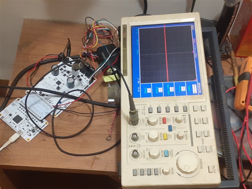
Can someone please share me detail on how to see trapezoidal wave in TMC9660 driver board using osciloscope.
  • Sign in to reply
  • Cancel

Top Replies

  • beacon_dave
    beacon_dave 14 days ago in reply to manojroy123 +2
    Looks like 'VM is not available' is one of the error conditions that would cause it to light. Another reference to checking the power supply if the error LED glows:
  • jc2048
    jc2048 18 days ago in reply to Jan Cumps +1
    Yes. The schematic shows them connected to GND.
  • jc2048
    jc2048 17 days ago in reply to manojroy123 +1
    I can't help you much with the controller or the motor side of things. You aren't going to see a trapezoidal waveform, whatever you do, because it's a velocity profile you're looking at in the diagram…
Parents
  • manojroy123
    0 manojroy123 19 days ago

    image

    Still no output even after executing command from direct mode. 

    • Cancel
    • Vote Up 0 Vote Down
    • Sign in to reply
    • Verify Answer
    • Cancel
  • Jan Cumps
    0 Jan Cumps 18 days ago in reply to manojroy123

    Is that mounting point grounded?

    image

    • Cancel
    • Vote Up 0 Vote Down
    • Sign in to reply
    • Verify Answer
    • Cancel
  • jc2048
    0 jc2048 18 days ago in reply to Jan Cumps

    Yes. The schematic shows them connected to GND.

    • Cancel
    • Vote Up +1 Vote Down
    • Sign in to reply
    • Verify Answer
    • Cancel
  • manojroy123
    0 manojroy123 18 days ago in reply to Jan Cumps

    Yes

    • Cancel
    • Vote Up 0 Vote Down
    • Sign in to reply
    • Verify Answer
    • Cancel
  • manojroy123
    0 manojroy123 17 days ago in reply to manojroy123

    Can someone please help with the TMC9660 driver board.

    • Cancel
    • Vote Up 0 Vote Down
    • Sign in to reply
    • Verify Answer
    • Cancel
Reply
  • manojroy123
    0 manojroy123 17 days ago in reply to manojroy123

    Can someone please help with the TMC9660 driver board.

    • Cancel
    • Vote Up 0 Vote Down
    • Sign in to reply
    • Verify Answer
    • Cancel
Children
  • jc2048
    0 jc2048 17 days ago in reply to manojroy123

    I can't help you much with the controller or the motor side of things.

    You aren't going to see a trapezoidal waveform, whatever you do, because it's a velocity profile you're looking at in the diagram, not a voltage waveform (as Doug helpfully pointed out). In theory it could be reconstructed from the PWM waveforms, but presumably that gets a bit messy because they're also sequencing round the phases. But you should at least be able to see each of the PWM waveforms from the three half-bridge outputs and see the mark-space ratio change to take the velocity up and down. They'll switch almost to the rails. If you aren't used to using an oscilloscope, set a vertical range that can fit 24V on the screen (5V per division would do), move the trace to the bottom of the screen, set the trigger to about halfway up (12V), set the timebase to something like 1ms per division (the PWM is somewhere between 1kHz and 100kHz, so that will at least show you something). I would have thought you'd see something briefly, maybe just a few cycles, even if the controller isn't happy and immediately shuts things down again (put the trigger on manual or one-shot and slow the timebase to capture all of the activity, if it is just a short burst of activity, and then work your way along the captured waveform using the zoom facility, or whatever you scope has). The exception might be if there's a direct short across two of the outputs - the controller could see that with the current sensing and might shutdown quickly (10s of microseconds) to protect the MOSFETs. Are there any registers in the controller that give status of these kind of events?

    If the controller does run briefly and then shuts down, you could try probing the 24V motor supply with the oscilloscope. When you start the motor, does the supply collapse? I don't mean sitting down a little because of the increased current draw, I mean a lot because it's limiting on the current. If so, you'll need a more capable PSU.

    Also you could try probing the hall effect sensor lines. Disconnect the motor drive connector and turn the motor shaft by hand. Do you see waveforms coming back from the sensor? If you have the controller set to operate closed-loop, it's not going to be very happy if it can't see any feedback and may treat that as a fault condition.

    • Cancel
    • Vote Up +1 Vote Down
    • Sign in to reply
    • Verify Answer
    • Cancel
  • jc2048
    0 jc2048 16 days ago in reply to jc2048

    I've just returned from walking to the shops to buy some groceries. On the way I realised that, of course, it only takes two half-bridges to make a full bridge so, with three outputs, at any instant one will be undriven and after settling will presumably end up at the half level (the motor Y configuration connecting it to the midpoint of two equal inductors connected between the rails), so suggesting 12V for the trigger level wasn't very inspired. Go higher or lower.

    So, if I'm now understanding it correctly, the PWM is there to control the current, so it can adapt to different motors and circumstances, not the velocity which comes from the rate of sequencing round the phases.

    Sorry for any confusion - I did say I didn't know a lot about motors and their controllers.

    • Cancel
    • Vote Up 0 Vote Down
    • Sign in to reply
    • Verify Answer
    • Cancel
  • Jan Cumps
    0 Jan Cumps 16 days ago in reply to jc2048
    jc2048 said:
    You aren't going to see a trapezoidal waveform, whatever you do, because it's a velocity profile you're looking at in the diagram, not a voltage waveform (as Doug helpfully pointed out)

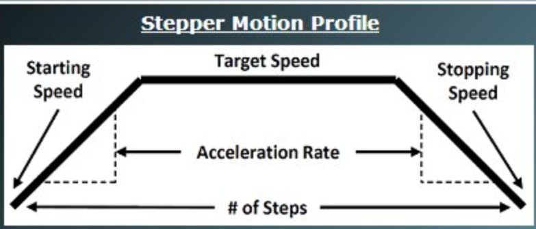
    Yes, This is a capture of a trapezoidal I did for a stepper motor project,

    image

    Velocity profile is visible because the frequency at the begin ramps up, then stable in the middle, then ramps down.
    image

    • Cancel
    • Vote Up 0 Vote Down
    • Sign in to reply
    • Verify Answer
    • Cancel
  • Jan Cumps
    0 Jan Cumps 16 days ago in reply to Jan Cumps

    Ow, just remembered that the road test is for a brushless DC motor ...

    • Cancel
    • Vote Up 0 Vote Down
    • Sign in to reply
    • Verify Answer
    • Cancel
element14 Community

element14 is the first online community specifically for engineers. Connect with your peers and get expert answers to your questions.

  • Members
  • Learn
  • Technologies
  • Challenges & Projects
  • Products
  • Store
  • About Us
  • Feedback & Support
  • FAQs
  • Terms of Use
  • Privacy Policy
  • Legal and Copyright Notices
  • Sitemap
  • Cookies

An Avnet Company © 2025 Premier Farnell Limited. All Rights Reserved.

Premier Farnell Ltd, registered in England and Wales (no 00876412), registered office: Farnell House, Forge Lane, Leeds LS12 2NE.

ICP 备案号 10220084.

Follow element14

  • X
  • Facebook
  • linkedin
  • YouTube