I can't help you much with the controller or the motor side of things.
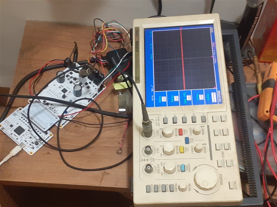
You aren't going to see a trapezoidal waveform, whatever you do, because it's a velocity profile you're looking at in the diagram, not a voltage waveform (as Doug helpfully pointed out). In theory it could be reconstructed from the PWM waveforms, but presumably that gets a bit messy because they're also sequencing round the phases. But you should at least be able to see each of the PWM waveforms from the three half-bridge outputs and see the mark-space ratio change to take the velocity up and down. They'll switch almost to the rails. If you aren't used to using an oscilloscope, set a vertical range that can fit 24V on the screen (5V per division would do), move the trace to the bottom of the screen, set the trigger to about halfway up (12V), set the timebase to something like 1ms per division (the PWM is somewhere between 1kHz and 100kHz, so that will at least show you something). I would have thought you'd see something briefly, maybe just a few cycles, even if the controller isn't happy and immediately shuts things down again (put the trigger on manual or one-shot and slow the timebase to capture all of the activity, if it is just a short burst of activity, and then work your way along the captured waveform using the zoom facility, or whatever you scope has). The exception might be if there's a direct short across two of the outputs - the controller could see that with the current sensing and might shutdown quickly (10s of microseconds) to protect the MOSFETs. Are there any registers in the controller that give status of these kind of events?
If the controller does run briefly and then shuts down, you could try probing the 24V motor supply with the oscilloscope. When you start the motor, does the supply collapse? I don't mean sitting down a little because of the increased current draw, I mean a lot because it's limiting on the current. If so, you'll need a more capable PSU.
Also you could try probing the hall effect sensor lines. Disconnect the motor drive connector and turn the motor shaft by hand. Do you see waveforms coming back from the sensor? If you have the controller set to operate closed-loop, it's not going to be very happy if it can't see any feedback and may treat that as a fault condition.
I can't help you much with the controller or the motor side of things.
You aren't going to see a trapezoidal waveform, whatever you do, because it's a velocity profile you're looking at in the diagram, not a voltage waveform (as Doug helpfully pointed out). In theory it could be reconstructed from the PWM waveforms, but presumably that gets a bit messy because they're also sequencing round the phases. But you should at least be able to see each of the PWM waveforms from the three half-bridge outputs and see the mark-space ratio change to take the velocity up and down. They'll switch almost to the rails. If you aren't used to using an oscilloscope, set a vertical range that can fit 24V on the screen (5V per division would do), move the trace to the bottom of the screen, set the trigger to about halfway up (12V), set the timebase to something like 1ms per division (the PWM is somewhere between 1kHz and 100kHz, so that will at least show you something). I would have thought you'd see something briefly, maybe just a few cycles, even if the controller isn't happy and immediately shuts things down again (put the trigger on manual or one-shot and slow the timebase to capture all of the activity, if it is just a short burst of activity, and then work your way along the captured waveform using the zoom facility, or whatever you scope has). The exception might be if there's a direct short across two of the outputs - the controller could see that with the current sensing and might shutdown quickly (10s of microseconds) to protect the MOSFETs. Are there any registers in the controller that give status of these kind of events?
If the controller does run briefly and then shuts down, you could try probing the 24V motor supply with the oscilloscope. When you start the motor, does the supply collapse? I don't mean sitting down a little because of the increased current draw, I mean a lot because it's limiting on the current. If so, you'll need a more capable PSU.
Also you could try probing the hall effect sensor lines. Disconnect the motor drive connector and turn the motor shaft by hand. Do you see waveforms coming back from the sensor? If you have the controller set to operate closed-loop, it's not going to be very happy if it can't see any feedback and may treat that as a fault condition.
I've just returned from walking to the shops to buy some groceries. On the way I realised that, of course, it only takes two half-bridges to make a full bridge so, with three outputs, at any instant one will be undriven and after settling will presumably end up at the half level (the motor Y configuration connecting it to the midpoint of two equal inductors connected between the rails), so suggesting 12V for the trigger level wasn't very inspired. Go higher or lower.
So, if I'm now understanding it correctly, the PWM is there to control the current, so it can adapt to different motors and circumstances, not the velocity which comes from the rate of sequencing round the phases.
Sorry for any confusion - I did say I didn't know a lot about motors and their controllers.
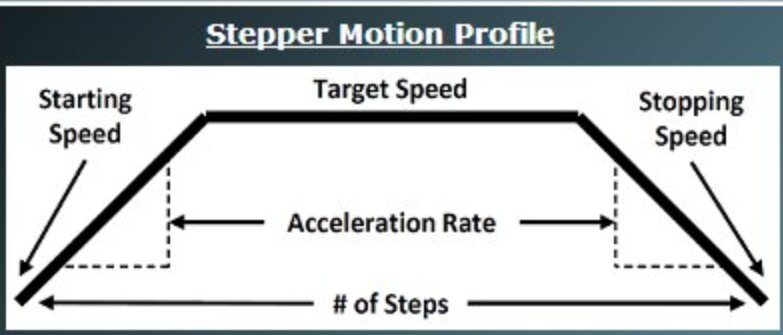
You aren't going to see a trapezoidal waveform, whatever you do, because it's a velocity profile you're looking at in the diagram, not a voltage waveform (as Doug helpfully pointed out)
Yes, This is a capture of a trapezoidal I did for a stepper motor project,
Velocity profile is visible because the frequency at the begin ramps up, then stable in the middle, then ramps down.