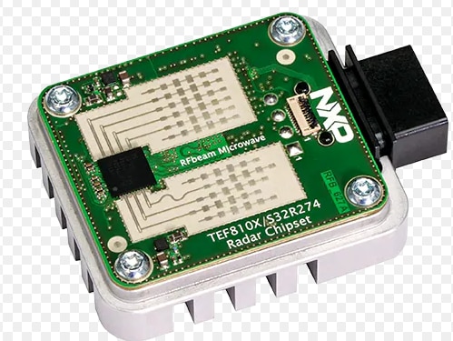
We have the opportunity to offer up the STEMlab 125-14 PRO Gen 2 Starter Kit - which is available on our online store .
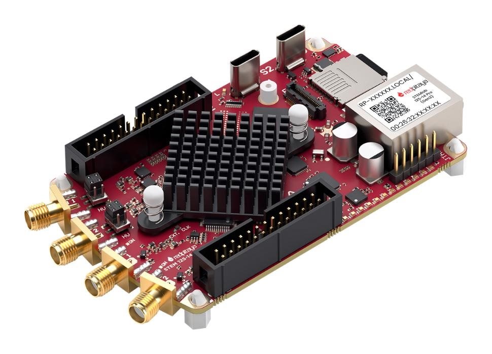
Here's a little bit about the hardware:
What do you think?
We have the opportunity to offer up the STEMlab 125-14 PRO Gen 2 Starter Kit - which is available on our online store .

Here's a little bit about the hardware:
What do you think?
I think it would be very useful in teaching and in research as well.
Very intersted Module that you can program it with Python, Matlab, Labview, C, etc....
With the FPGA on the STEMlab 125-14 PRO Gen 2 (Zynq-7010), you’re essentially sitting on a real-time, deterministic signal-processing fabric that can ingest the 2× 125 MS/s ADC streams, process them with sub-µs latency, and drive the 2× 125 MS/s DACs—while the ARM cores handle UI/networking/logging.
The STEMlab 125-14 PRO Gen 2 appears to use a web-based interface for different applications, explained in more detail here.
The linked page is also the landing page for the other control methods available. There is the option available to control it using MATLAB, LabVIEW, and Python, or to program your own applications making use of provided APIs to run C code and Python (using Jupyter notebook) or create and run your own FPGA Logic.
I would be happy to roadtest this! I would use it to experiment with logic tester results for my embedded projects.
Thanks for the reference community.element14.com/.../scottiebabe
An interesting project but the Red Pitaya involvement was not very significant and their hype is a bit irksome.
Full kudos to the student for the real RF work - but it was done at 2.4GHz and the RP was only operating at much lower frequencies.
They said:
Red Pitaya bridges the gap between theoretical RF engineering and practical hardware design. With its 125 Msps ADC, FPGA, and built-in ARM processor, it lets students digitize high-frequency signals, run real-time processing, and control the entire radar system — all on a single board.
But then they say:
Here’s what made David’s DIY FMCW radar project possible with Red Pitaya:
Operating Frequency: 2.4–2.5 GHz
Sweep Rate: 1 kHz
Transmit Power: 26 dBm (400 mW)
ADC Sampling Rate: 125 Msps (14-bit resolution)
Core Capabilities: Simultaneous distance and velocity measurement
The RP can't do anything useful at 2.4GHz, and it has no influence at all on transmit power.
So the RF design would have required the usual RF gear and software.
It would be nice to know what software was used to design the mixer and other RF stuff and how it was tested.
In this design the RP generates a 1kHz ramp to modulate the VCO and measures the beat frequency of the RF return signal with the local oscillator (actual frequencies not disclosed).
It doesn't look as if the RP is doing anything a £25 ST Nucleo board couldn't do.
The Red Pitaya is an interesting and potentially useful product but over-hyping the way they do does no one any favours.
MK
If one is provided free of charge, I would be interested in reviewing one, and providing a report. My project would be a Q-meter for measuring inductors, which would also give inductance. This would not use the technique used in your LCR meter application, which has a few fixed frequencies. A standard LCR meter, even the latest models from Keysight, are not accurate on Q measurements of inductors of even a modest Q (>20). We have for comparison purposes
* Agilent 4284A Precision LCR meter 20 Hz to 1 MHz (basic accuracy 0.05%) www.keysight.com/.../5963-5390.pdf
* HP 4285A Precision LCR meter 75 kHz to 30 MHz (basic accuracy 0.1%) www.keysight.com/.../5963-5395.pdf
* A very old Boonton Q-meter, which has lower uncertainty than the more modern HP:Agilent//Keysight instruments.
* VNAs covering the frequency range 300 kHz to 20 GHz.
* Boonton inductors of various values, with accurate measurements of both inductance and Q.
The proposed Q-meter would rely on a measurement of 3 dB bandwidth of a resonant circuit, where a low-loss manually tuned variable capacitor is adjusted to provide resonance at the frequency required.
There is an example in the 4285A manual and datasheet showing the calculation of uncertainty for an inductor. At a frequency of 25.2 MHz, inductance of 220 nH, and measured Q of 30, the uncertainty in inductance is ±2.6%, but for Q it is −13 /+105. Thus, the Q could lie anywhere from 17 to 135. The instrument’s basic accuracy of 0.1% therefore does not translate into an accurate measurement of Q. I think this illustrates the point that even a high-end professional LCR meter is not suitable for precise Q measurements.
Agilent did manufacture a precision Q adapter (42851A) for the 4285A. We do not have one of these, and they are around $2,500 on the used market. However, I have a good understanding of how it operates and believe a Red Pitaya could form the basis of a meter able to measure Q much more accurately than any affordable modern instrument. Comparisons with VNA measurements would yield interesting results. What is the most accurate method? Under what conditions?
Being provided the LCR meter add-on would be useful for comparison purposes, but ultimately the LCR meter functionality will be poor compared to other instruments we have. But if a Q-meter was built, it could be sold as an ad-on as Agilent did with the 4285A+42851A.
Dr. David Kirkby BSc, MSc, PhD.
Looks farm more exciting than the current modules...

I'd like to strap one of those on my bumper and watch the cops go nuts.