RoadTest: Panasonic Laser PM2.5 (Dust/Smoke) Sensor w/ MCU - Industrial Sensing
Author: genebren
Creation date:
Evaluation Type: Test Equipment
Did you receive all parts the manufacturer stated would be included in the package?: True
What other parts do you consider comparable to this product?: The addition of a mating cable for the sensor was a good thing, but having already found a suitable solution to that problem it was too late for me.
What were the biggest problems encountered?: The communication specification was lacking and the need for a 'repeated start' and a delay prior to reading data made the I2C communication with this device to be very problematical. The UART communications while infinitely simpler, provided less resolution and range than the I2C method, forcing my hand to spend a significant amount of time to develop (hack/port/code/test) a reliable method of communicating with the device via I2C.
Detailed Review:
My proposal for this roadtest included a description of three tests that I will perform using the Panasonic Dust/Smoke Sensor (since that time I have thought of a few other tests that I might want to add to the list if I have available time). Here are the tests that I intend to perform with this sensor.
Unfortunately, life had other plans. I recently re-injured my shoulder and I currently restricted in motion and dexterity so I needed to leave out the A/C testing as that would require climbing around the attic which was no quite practical given the sling on my right arm. Also, the filaments that I ordered to test particle/concentration counts during printing have still not arrived. I continued with the testing the effectiveness of my solder fume extractor and added a new test for measure the filter effectiveness of a KN95 mask versus a generic cloth mask.
In order to complete these tests, I needed to have multiple sensors. I utilized a portion of my project14 "Off the Shelf" prize to buy a pair of the Panasonic sensors (always nice to have a spare, just in case). Next I needed to design a suitable logging instrument to host the sensors in a remote environment. For this task, I decided on the following specifications:
Using these specifications, I generated a design for my dust data logger module, ordered PCBs and built my first prototype. Initially, I had intended to extract data from the Dust/Smoke sensor using I²C, after doing a more thorough read of the communications specification of the Panasonic module, I noticed that they were calling out the use of a repeated start condition between the write Address and the read of Data. Furthermore, they called out a wait period of 500uS between the sending of the slave address and the receipt of data during the read sequence. The library that I use for I²C does not handle the 'repeated start' or have a way to insert a delay into the read process, so I needed to shift gears and look into the UART data stream. After determining that the UART communications provided less resolution and range than the I²C method, forcing my hand to spend a significant amount of time to develop (hack/port/code/test) a reliable method of communicating with the device via I²C. Initially I started by porting a copy of the Arduino I²C library into my CodeVisionAVR compiler. This did a good job of addressing the Repeat Start, but all attempts to embed a selectable delay into the process failed. I then shifted gears and used a bit banged approach to write a suitable communications package. This worked and allowed me to begin to understand the data format of the density readings (32-bit variable 1000 times the mass-dennsity). The bit-banged approach proved to not be reliable enough as several reads would fail (bad/late ACKs and/or shortened read sequences). After more reworking of my ported IC2 library, I had a few breakthroughs and I was able to reliably read the density value. As I then started collecting data, I came to notice a flaw in my compilers ability to convert long integers into strings (sprintf ("%lu", density)). So I needed to modify my readings of vales saved into the EEPROM to send out the density values as a pair of integers and then convert them into a long integer inside the EXCEL worksheets.
The details of the hardware designs are contained in the following blogs:
Here is a scope capture of the functioning of the reworked I2C library, showing a query of the Smoke/Dust sensor, reading the PM and Particle counts, followed by a query of the status register:

Solder fume extractor tests
In this test I wanted to see how effective my Multicomp Pro MP740146 Soldering Fume Extractor Multicomp Pro MP740146 was in removing soldering fumes.

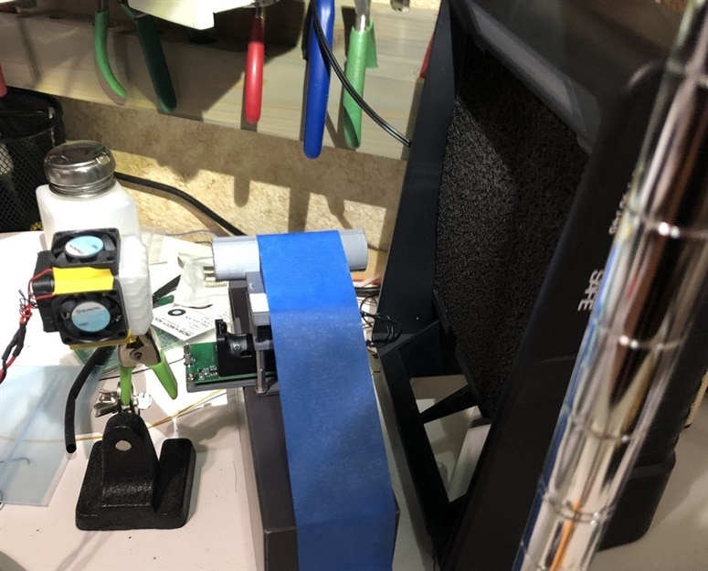
Here are the Dust Data Logger modules and the test setup for the Multicomp MP470146 test.


After several attempts of getting a reasonable result in the tests, it became clear that I needed to convert the smoke from soldering into a stream that would reliably pass through the sensor and to the fume extractor. To achieve a consistent flow of smoke I re-purposed a fan assemble (fan cube) to draw in the soldering smoke, mix it and force the air towards the intake of the sensor (partially hiding under the blue painters tape that secures it in place). On the back side of the fume extractor, the second sensor samples the exhaust air of the fume extractor. To run the test I would melt solder just below the fan cube (to avoid solder drips I would wipe down the soldering iron tip before it could splatter and leave a mess). The two dust data loggers were powered from an external power source so I could bring up the module together. After running the tests I would use a PC based monitor program to upload the log files from the two devices. I would copy the files into and editor and strip out some of the text and create a comma separated record that I could import into Excel. I would then use Excel to create plots and statistics that I could use to measure the degree of fume extraction.
In this test, I started the sensors and waited for the initial stability time (30 seconds) and then started melting solder for about 40 seconds. I then wait about 40 seconds then started another solder melting for about 60 seconds and then wait about 40 seconds before shutting down the data loggers. Here are some of the plots that I acquired from this test:


The first chart shows the Mass Density data recorded during the test. The second chart show the particle count of the test. The third char shows the same particle counts, but moves the last six traces to a secondary axis to show a little more of the shape of these traces. The small dip in the center of the second soldering period shows the result of a tip wiping interval that allow the count to drop significantly. These larger size particles have a pretty significant effect on the Mass Density reading as the particles are larger, this is shown in the depth of the center dip in the Mass Densities, that is much greater than the dip in the particle counts of the most reactive sizes (0.3-0.5µm and 0.5-1.0µm), but still seen to some degree in some of the larger particle sizes (2.5-5.0µm and 5.0-7.5µm).


The first chart shows the Mass Density data recorded during the test. The second chart show the particle count of the test. It appears the Fume Extractor did a pretty good job of filtering out the particulate matter, with the possible exception of the 0.5-1.0µm range. Lets look a little closer on the differences between the intake and exhaust values:

Overall the Mass Densities were reduced by >97% while the particle counts were reduced by a range of >72% to >98%, with the filter performing marginally in the 0.3-0.5µm and 0.5-1.0µm channels (this result again points to the significance of the large particle sizes in all of the Mass Density channels).
KN95/Cloth Mask tests
In this test I wanted to evaluate the performance of a generic cloth mask to a KN95 mask. Here is the test setups for the two mask types:


In this test setup a 5 1/2" length of 2" ABS pipe is used to hold the fan cube (directly behind the mask to draw air through the mask) and the exhaust side sensor (data logger). The mask is held in place with the straps, effectively sealing the mask to the pipe. This test used an incense stick as the smoke source (positioned in front of the intake sensor. In these tests, the smoke was applied to the mask for ~30 seconds and removed for ~30 seconds. I first tested the KN95 mask and then the cloth mask.
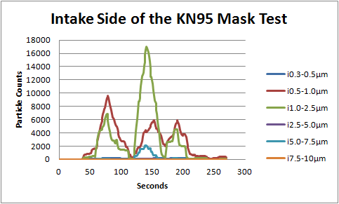
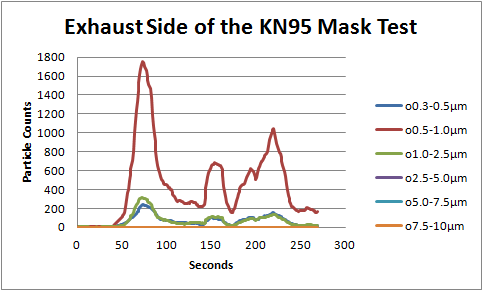
Here are the results from the KN95 mask test:


Looking at the first peak in the test sequence there is almost equal amounts of Mass Density in all channels, while second peak has nearly a 50% reduction in Mass Density (also the amount of 1.0-2.5µm particles in the second peak is almost twice as high as in the first peak). Throughout these tests it was difficult to position the smoke source such that it was obvious that the smoke was in fact entering the intake sensor. In order to determine the mask filtering I took two sets of statistics (the whole trace versus the initial peak) to see what effects, if any, were seen in the results.


Looking at the exhaust side readings, it seems to show a much lower reading for the second peak, so this too points to an inconsistency in the smoke flow between the two sensors. Next I computed two sets of statistics for this test setup.

Looking at the statistics, the KN95 mask reduced all of the Mass Densities of the smoke by >98%, while the particle counts were reduced in the range of 22% to 100% across the full test and 14% to 100% across the first peak. The estimated size of a respiratory particle is 4.7 µm which filtered very well by the KN95 mask.
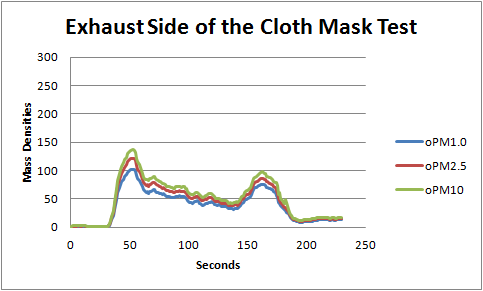
Next the cloth mask was tested using the same setup. Here are the results for the cloth mask:


Looking at the final peak in the test sequence there is almost equal amounts of Mass Density in all channels, while first two peaks are almost not present Throughout these tests it was difficult to position the smoke source such that it was obvious that the smoke was in fact entering the intake sensor. In order to determine the mask filtering I took two sets of statistics (the whole trace versus the final peak) to see what effects, if any, were seen in the results.


Looking at the exhaust side readings, it seems to show a much higher reading for the first and second peak than reflected in the intake side readings, so this too points to an inconsistency in the smoke flow between the two sensors. Next I computed two sets of statistics for this test setup.

Looking at the statistics, the Cloth mask reduced all of the Mass Densities of the smoke by >98% (<99% for the Final Peak), while the particle counts were reduced in the range of 41% to 100% across the full test and 46% to 100% across the final peak. The estimated size of a respiratory particle is 4.7 µm which filtered very well by the cloth mask.
Conclusions
First a big thanks to element14 and Panasonic for selecting me as one of the RoadTesters for this product. While I was very impressed with the quality and performance of the this device, I was not at all impressed with the communications for getting the data. While UART data was an easy read, the limited precision and range of the Mass Density readings was disappointing. The I2C side of the communications felt like a complete hack. The delay should not have been necessary, instead the module could have utilized clock stretching to hold up the bus until the data was ready. The register map for the device seemed to like a hack, with fixed data embedded in between variable data entries made it necessary to read more data that should have been required. In all, the work required to integrate this sensor into a working product was a huge effort instead of a simple drop in.
I do plan to revisit my tests on both my A/C unit and 3D Printer as my shoulder improves and I have more time available.