Experiments with USB PD 3.0 Power Supply

Table of contents

RoadTest: InnoSwitch 3-Pro GaN Controllable USB Power Supply

Author: skruglewicz

Creation date:

Evaluation Type: Development Boards & Tools

Did you receive all parts the manufacturer stated would be included in the package?: True

What other parts do you consider comparable to this product?: PAT Tester

What were the biggest problems encountered?: I found it hard to figure out a way to report a useful review due to the lack of examples and experiments to test the board. I could not get any USB tester to work with the USB connector? The only device it would charge was my smartphone using a type-C to type-C connector.

Detailed Review:

`This review will cover the evaluation of a USB PD 3.0 Power Supply supplied by Power Integrations (power.com). The part number for the board is RDK-802. The Board contains a InnoSwitch 3-Pro GaN-based INN3379CH302 and a Weltrend WT6635P USB Controller..
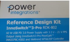
It contains a USB Power Delivery Revision 3.0 connector, which  allows for delivery of power up to 100W through a single cable. The specification makes it possible to power multiple devices simultaneously, eliminating the need for a dedicated AC adapter for each device. This USB is a PPS using highly optimized, low pin count USB PD controller WT6635P. What is USB PD PPS? it's a Programmable Power Supply (PPS) which  is a standard that refers to the advanced charging technology for USB-C® devices. It can modify in real time the voltage and current by feeding maximum power based on a device's charging status.
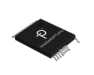
There is a I2C Interface that enables low pin count USB PD controller (10 pin).. Unfortunately PI tech support has verified that you will need to remove the  USB controller, by de-soldering it from the board. An option that I am not willing to do, but I do give information on links to how to use an Arduino Uno and connect it via I2C, later in the review. 

I do not have much experience with power supplies, but I am interested in learning more.
I have been using power from the USB cable to power all the projects I've been doing here on element14. I recently finished a Design challenge that I powered first with 2 3.v AA batteries, but then I needed 5 v to power the sensors in the project. The electronics were remote so I powered it with a charger.
I would like to conduct some experiments from a beginners point of view to learn about this technology. I would like to implement a power supply that I could use to power my Remote Monitoring Projects. These projects require various power requirements to operate.

I have participated in 7 Road-tests and 4 Design Challenges on element14.com. I have worked with EVK's from NXP, Lattice, Renesas, Infineon and Cypress. I have also done experimenting with the several models of the Raspberry PI. 

My background is more on the software side, with a Bachelors of Science Degree in Computer Science from Boston University.
I Graduated from BU in 1980 and had been working as a Software Engineer since then until I retired in 2018.
I've been presently experimenting with IoT and I've used many Development kits. 

I will be evaluating the use and helpfulness of customer support on the the website. I will also be discovering and evaluating the available User Forums and Knowledge Base available on the  Site, that hopefully will aid me in my experiments. I will also be using the Resources (Documentation  Reference Design Kit RDK, Video's, Tutorials ) available on the Website. I will be including links throughout my review and in the "references" section at the end of this review.

Unboxing

I received the package containing the Reference Design Kit RDK802 for the InnoSwitch3 Pro  on Monday April 4, 2022. The box contents contained the board and a power chord with 4 different plug adapters. The back of the       box displays a QR Code that takes you to the document  RDR-802 mentioned in this review

What comes in the Box

{tabbedtable}Description
The contents image
The Board BACK                                                  FRONTimage
QR Code image
The BOX image

Available Resources

Documents

  • RDR-802 60 W InnoSwitch3-Pro USB PD 3.0 with PPS
    • Document Number RDR-802 engineering report
    • This document is an engineering report describing the 60 W USB PD power supply being reviewed. The application described in this document, is for a phone charger. It is authored by the  companies Applications Engineering Department. It contains specification, schematic diagram, printed circuit board layout, bill of materials, transformer documentation, and performance data for components on the board.
    • This is the only document that I could find on experimenting with the board. To be perfectly honest, this document is way over my head. I do not recommend it  for an intermediate electronic hobbyist such as myself. 
    • The board primary purpose seems to be to evaluate using the InnoSwitch TM 3-Pro GaN-based INN3379CH302 and Weltrend WT6635P Controller. 

Website  Resources

I thought I would try and find out more about the kit on the website. I  thought to check out some resources on the site. I decided to try and ask some question on the customer support and forums,, to find out if there were more experiments that were more suitable for a novice  maker like myself. 

Documents,

Customer Support,

  • I contacted support with an inquire on March 30,2022. I put in a request into both Technical Support  and Request Design Assistance 
    • I requested some guidance on using the kit. And if there were any other tutorials available for the product 
    • I received a response from tech support on Mar 31, 2022, A day later, good turn around time. I Never heard back from Design Support?
  • An Application engineer came back with 2 other experiments that I could try. One involves purchasing a Power Adapter Tester (PAT) for $50 and the other involved modifying the board by de-soldering the built in USB built in controller and  control the InnoSwitch3-Pro directly through I2C using an Arduino  These 2 solutions required an extra purchase and hacking the board which I do not feel comfortable with doing. I have noted the recommendations in the (Examples, Experiments, Tutorials) section below, for those of you who are interested
  • I found the support site to be cumbersome to use and needed to enter in too much information to open up a simple ticket. The response is strictly by email. And there is no way of following up on the ticket online.

Forums

  • I wasn't able to find any on the forums

Examples, Experiments, Tutorials

Recommend experiments

  • The 2 recommended experiments suggested by PI Tech Support. One involves purchasing a Power Adapter Tester (PAT) for $50 and the other involved modifying the board by de-soldering the built in USB built in controller and  control the InnoSwitch3-Pro directly through I2C using an Arduino  
    1. The InnoSwith3-Pro is dynamically controlled through an I2C interface. Seeing as the kit you are provided already has a USB PD controller on the circuit board I would suggest you purchase a USB PD Power Adapter Tester (PAT) Tool. It will be a circuit board that can interface with the USB C output of the RDR-802. The PAT tool is controlled by a computer through USB and can request any output voltage or current from the RDR. We recommend the
    2. If you are comfortable modifying the hardware you may de-solder the built-in USB PD controller and control the InnoSwitch3-Pro directly through I2C using an Arduino. You may use the AN-85 - InnoSwitch3-Pro Master Debugger User’s Guide (requires DFROBOT LCD Keypad Shield V2.0) or AN-77 - InnoSwitch3-Pro Code Library using Arduino (Arduino only) to get you started. Here is the InnoSwitch3-Pro Code Library and API for Arduino.

Connected to My smartphone.

  • I connected the board to my smart phone With a type-c USB cable
  • It took about 1 hour and 45 minutes to charge to !00% from 15%. 
  • This is a little slower than the Fast charger supplied to me with my smart phone.

USB Tester

  • I purchased and used a "Type-C Voltage and Current USB tester from amazon https://www.amazon.com/dp/B07MGQZHGM?psc=1&ref=ppx_yo2ov_dt_b_product_details
    • image
  • This was my first experience with USB testes. Initially I connected it to the RDK with an OTG adapter as described in the Photo below. It registered at 5.077 volts. I later learned how to use the Type-C input as described in the next section
    • image

More Testing

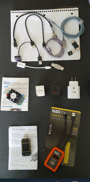
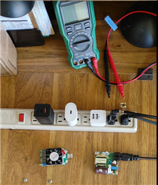
  • Using different Power sources, USB Testers, various USB cables and my LG V60 SmartPhone,  I compared different Power sources to the output of the RDK.
  • Power Sources
    • To compare the power out of the RDKI used the Following:
      •  LG USB Fast Wall Charger (25W) (This came with my phone)
      • Baseus 65W 3 Port Foldable USB C Fast PD GaN  Wall Charger ($30)
        • image
      • Anker Dual Port 12W Wall Charger (2 for $22)
  • USB Testers
    • In addition to the above mention USB tester, I purchased two additional testers form amazon.
      •  KJ-KayJI ($24)
        • image
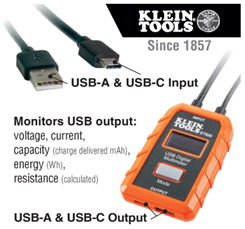
      • Klein Tools ET920 ($40)
        • image
  • Devices
    • DROK Electronic Load Test Resistor Module 25W
      • image
    •  LG V60 SmartPhone
  • USB Cables
    • Type-C to Type-C
    • MicroUSB to Type A
    • Type-C to Type-A
    • OTG adapter (Type-c male to Type A female)
    • Adapter (Type-C female to Type A male)
  • What I discovered with the testers was that I needed to attach the type-C output to my smart phone before the Display would work. This was not so for the Type A input. I found this confusing at first, But I guess it makes sense.
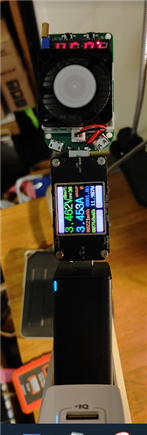
  • What I found was pretty identical from all power sources using the testers and appropriate USB cables
    • Using the SmartPhone
      • Type-C to Tester to Smartphone
        • RDK - 9,9V 1.39A
        • GaN wall Charger - 6.84V 1.11A
        • LG  wall charger - 6.98V 1.10A
      • Type A to TESTER to Type C adapter to Type-C on SmartPhone
        • Anker - 5.10 V ,44A
        • Gan Wall charger(USB type A Port) - 5.06 .44A
      • Type-C OTG to TESTER Type A input to Type C adapter to Type-C on SmartPhone
        • RDK - 4.98 V .44A
        • GaN - Type-C Port- 5.03 V .44A
        • GaN- Type-A Port = 5.05V .44A
    • Using the LoadTester
      • Type-C 
        • RTK - 5.2V 3.29A
        • GaN - 3.7V 4.09A
        • LG - 3.7V 4.09A
      • Type-A
        • Anker - 5.0V .015A
        • GaN Type-A port - 3.4V 3.5A
    • Powering an MCU
      • Finally, I was able to power on an Arduino project that I have been working on.
        • the Tester reported a voltage of 5.16 and an amperage of 0.09.

image

Summary & Conclusions

  • Before I received the kit,
    • in Reviewing the Roadtest landing page I didn't quit understand about the kit that I was selected to review.
    • The datasheet link was more like an engineering report on how to implement a Phone Charger. Not quit what I was expecting to learn and experiment with the product.
    • I started reading about the product
      • Browsing the website for more information on the product. I found there to be minimal information available on the product.
      • I was able to get 2 ideas from an Applications Engineer on the 2nd tier support email, which was helpful.
  • When I received the kit,
    • I was surprised to see that the RDK was a completely functional Type-C Phone charger.
    • I also charged my phone with it. 
    •  I wasn't  able to do the 2 ideas from an Applications Engineer on the 2nd tier support email. mentioned in my review.
      • The PAT tool was to expensive for me to purchase at this time.
      • The I2C experiment required the de-soldering of the on-board USB controller, which I did not want to chance ruining the RDK. It seems like an interesting experiment though
    • I purchased USB Testers, LoadTester and a GaN wall charger from amazon. 
      • Using the Purchased gear from amazon, I was able to experiment and compare the RDK to other power sources..
  • All in all an interesting product but not for the novice like myself to experiment with.
  • Scoring  - Why I scored the product like I did
    • Product Performed to Expectations (4 Stars)
      • Once I plugged in my phone the product charged my SmartPhone as I expected. The testing and Comparison to other power sources showed a slight improvement in Voltage and Amperage.
    • Specifications were sufficient to design with (3 Stars) 
      • The specs included is the only document available appears to contain all the data needed to design a circuit using the InnoSwitch3 Pro chip. But circuit design is way above my paygrade so I assume the specifications are sufficient.
    • Demo Software was of good quality (.5 Stars)
      • This ranking does not apply to this product, but no way to indicate it, so I gave it the lowest rating.
    • Product was easy to use (2 Stars)
      • Considering there was no programming involved and all that was needed was to plug a type-C compatible device into it, this product was easy to use.
      • But since the I2C interface is not supported without unsoldering the USB controller chip I gave this a 2 stars score. It would be nice to be able to By-Pass the USB controller and be able to experiment with I2C.
    • Support materials were available (2 Stars)
      • The only support material available on the RDK was the Report mentioned in this review. As a novice I would have liked to see more examples of how to experiment with the product.
    • The price to performance ratio was good (3 Stars)
      • I gave this a low score because I was able to get a GaN supported Wall Charger for a quarter of the price of this product. 

Future Enhancements

  • Purchase and Use the PAT tool, to test the board
  • Try out the other plugs that came with the RDK
  • Understand the Documentation.

References

https://www.power.com/  -  Home page of Power Integrators. You can register and get Tech support.

InnoSwitch3-Pro - Page Describing the InnoSwitch3-Pro

Anonymous
  • > This ranking does not apply to this product, but no way to indicate it, so I gave it the lowest rating.

    In that case I give it average of the other scores, so that the total value has some relation to the scores of those topics that did apply.