RoadTest: BeagleBone® AI-64
Author: kk99
Creation date:
Evaluation Type: Evaluation Boards
Did you receive all parts the manufacturer stated would be included in the package?: True
What other parts do you consider comparable to this product?: From the available SBCs it could be the Nvidia Jetson Nano B01. From the, incoming SBCs the StarFive VisionFive 2 will be comparable.
What were the biggest problems encountered?: There was no problem, but to start working with the board, the following points are required to be fulfilled: - have a proper power supply that delivers 5V and minimum 3.0 A current, - converter from miniDisplayPort to HDMI, - WiFi USB dongle or M.2 E card if we need wireless communication.
Detailed Review:
The package came to me by UPS. The kit contains:
- quick start guide,
- cardboard box,
- BeagleBone AI-64 board with assembled heatsink packed in antistatic foil.
| {gallery} Package |
|---|
|
Cardboard box |
|
Quick start guide |
|
BeagleBone AI-64 board top view |
|
BeagleBone AI-64 board bottom view |
|
BeagleBone AI-64 board ports |
|
BeagleBone AI-64 board UART connectors and M.2 E slot |
|
BeagleBone AI-64 board microSD card slot and FAN connector |
|
BeagleBone AI-64 board CSI connectors and DSI connector |
In this section I would like to highlight the major components and interfaces that make up the board to get a high level overview. Below there is a board specification with the features:
Processor: Texas Instruments TDA4VM
Graphics: PowerVR Series 8XE GE8430
Memory: LPDDR4 3200 MHz 4GB Kingston Q3222PM1WDGTK-U
Storage: eMMC 16 GB Kingston EMMC16G-TB29-PZ90
PMIC: TPS65941213 and TPS65941111
Debug Support: 2 x 3 pin 3.3V TTL UARTs: (Wake-up and main domain serial ports)
Ethernet: gigabit, RJ45, link/speed indicators
SD/MMC slot: microSD 1.8/3.3 V
USB-3.0 client port: access to USB0, SuperSpeed, dual-role mode via USB-C, no power output,
USB-3.0 host port: TUSB8041 4-port SuperSpeed hub on USB1, 2 x type A socket, up-to 2.8A total, depending on power input
Video output: miniDP
Audio output: stereo via miniDP
User input: reset button, boot button, power button,
Indicators: power and 5 user LEDs
Power source: USB-C or DC5.5/2.1mm Jack (5V, >3A)
PCB: 10.16 x 7.87 cm
Weight: 192 g with heatsink
The heart of the board is the Texas Instruments J721E-family TDA4VM system-on-chip (SoC) which is part of the K3 Multicore SoC architecture platform and it is targeted for reliability, low-latency, high performance, low power and security. Below there is a functional block diagram for this SoC architecture:
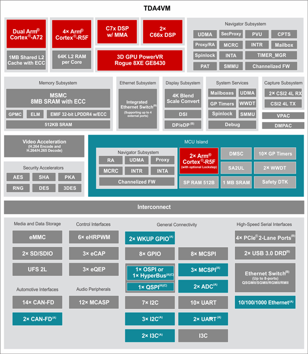
Further in the review I will focus on key features of this architecture, like accelerators, MCU and encoders/decoders.
Below there is an image with information about the locations of connectors, LEDs and switches description that will make it easier to initial configuration and operation of the board:

The board comes with a pre-installed Debian distribution with Xfce as a desktop environment ready to use out of the box. The board could be used in two configurations: a regular PC with connected display, keyboard and mouse and in headless mode. I have decided to use this board in a headless configuration. In this mode, is possible to access the system via SSH via Ethernet or USB virtual Ethernet. I have also decided to use WiFi USB dongle. Unfortunately, the selected dongle TP-Link Archer T2U Nano is not supported by the kernel by default. But it is easy to add, by installing dkms and downloading and installing the proper driver. Below there are steps to do that:
sudo apt-get install dkms
git clone git@github.com:aircrack-ng/rtl8812au.git
cd rtl8812a
sudo make dkms_install
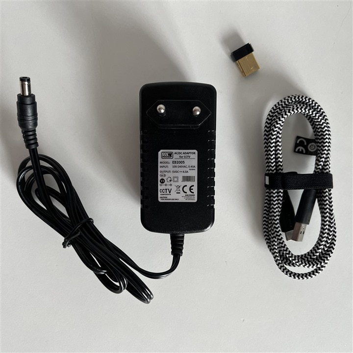
It may also be required to install a kernel headers for the current Linux version in the system before this step. After successful installation there is required just to edit wpa_supplicant config file with setting for our WiFi network. I have performed also update of all system packages to latest available version. I have installed also VNC server to have access for X window system. In the case of power supply, I have checked that powering the board via USB-C from a notebook is not enough. It is required to use an external power supply. Below there is image of adapter that I used:
I have started work with the BeagleBoard by performing benchmarks. I have found a here test suite that contained benchmarks for Raspberry Pi 4B and Nvidia Jetson Nano 4GB, so I decided to perform a test for BeagleBone to compare the results with them. I have installed the same version of The Phoronix Test Suite and configured it to perform the same benchmarks. Before performing the results, I also created a shell script to record to file the information from available thermal zones in the system to have information about how the board performs with the stock heatsink without a fan. Below there is source of this script:
#!/bin/sh

if [ "$#" -ne 1 ] || ! [ -d "$1" ]; then
  echo "Usage: $0 OUTPUT_DIR"
  exit 1
fi

MEASUREMENT_NUMBER=0;
while [ true ]; do
    for i in /sys/class/thermal/thermal_zone*; do
        echo "$MEASUREMENT_NUMBER,$(cat "$i"/temp)" >> $1/"temp_$(cat "$i"/type)"
    done
MEASUREMENT_NUMBER=$((MEASUREMENT_NUMBER + 1))
sleep 1;
done
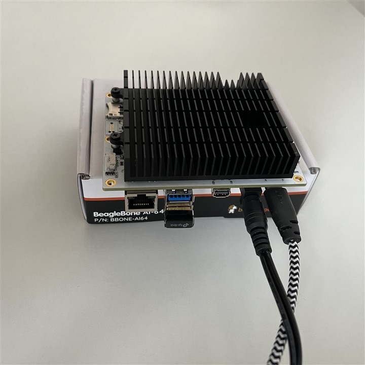
With this script running in the background I have started test suite. The ambient temperature during the test was around 24.3 degrees Celsius. The board was placed in the position as is seen in the attached image:
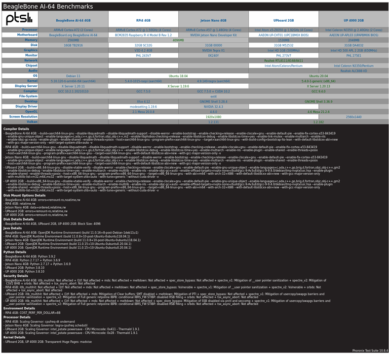
Execution of this test took over 2 hours. Results are below:
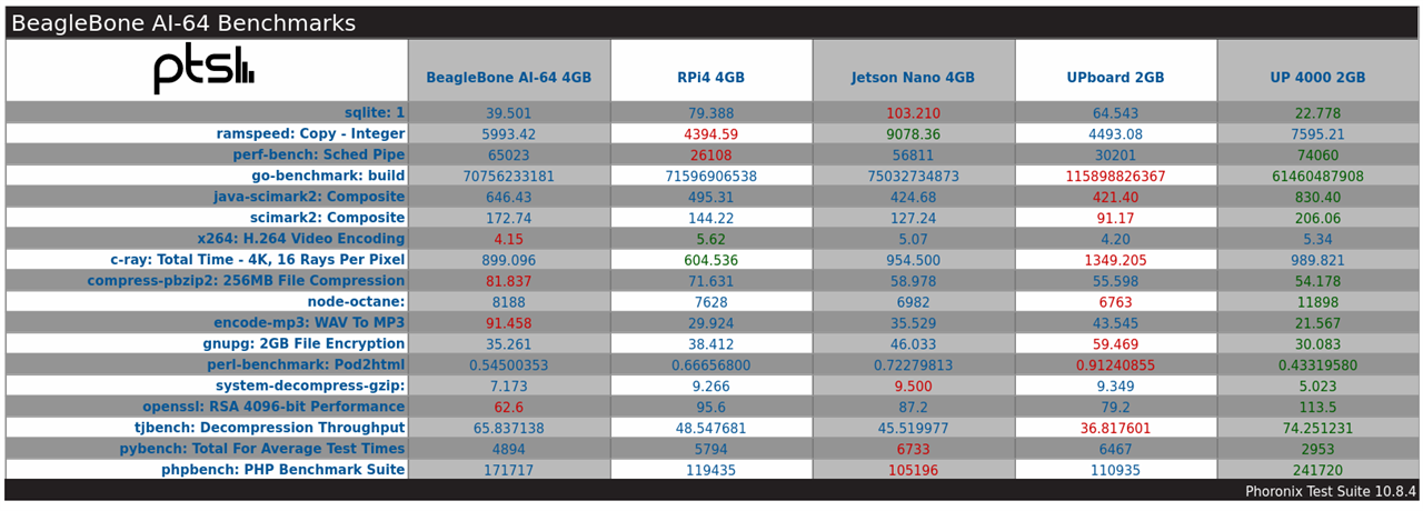
Below there are the results for each test:
| {gallery}PTS |
|---|
|
SQLite 3.30.1 |
|
RAMspeed SMP 3.5.0 |
|
perf-bench |
|
Go Benchmarks |
|
Java SciMark 2.0 |
|
SciMark 2.0 |
|
x264 2019-12-17 |
|
C-Ray 1.1 |
|
Parallel BZIP2 Compression 1.1.12 |
|
Node.js Octane Benchmark |
|
LAME MP3 Encoding 3.100 |
|
GnuPG 1.4.22 |
|
Perl Benchmarks |
|
System GZIP Decompression |
|
OpenSSL 1.1.1 |
|
libjpeg-turbo tjbench 2.0.2 |
|
PyBench 2018-02-16 |
|
PHPBench 0.8.1 |
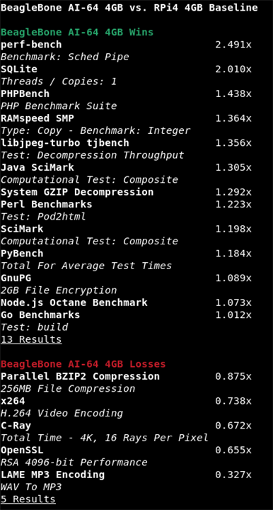
These tests are mainly focused on testing CPU, memory and storage usage. In my opinion, the results are good. If we compare side by side, for example, with Raspberry Pi4, we see that BeagleBoard wins in tests where it is used a single core. It is as expected because the BeagleBone uses the same ARM Cortex-A72 but with a higher allowed frequency, up to 2 GHz. Also, the built-in eMMC could also influence some tests if we comapre it to the MicroSD card available in RPI4. Below there is image with comparison of BeagleBone with Raspberry Pi 4:
The results of cooling with the stock heatsink are also fine. Below there is a plot that presents temperature changes during the tests:

The two falling slopes between 2000 and 4000 seconds are caused by cooling for a few seconds the heatsink with small air flow. I was curious how fast the temperatures would rise to base level during the test.
I have also performed a few tests for graphics, like:
- glxgears,
- Speedometer 2.0,
- GLmark2.
Below there are results:
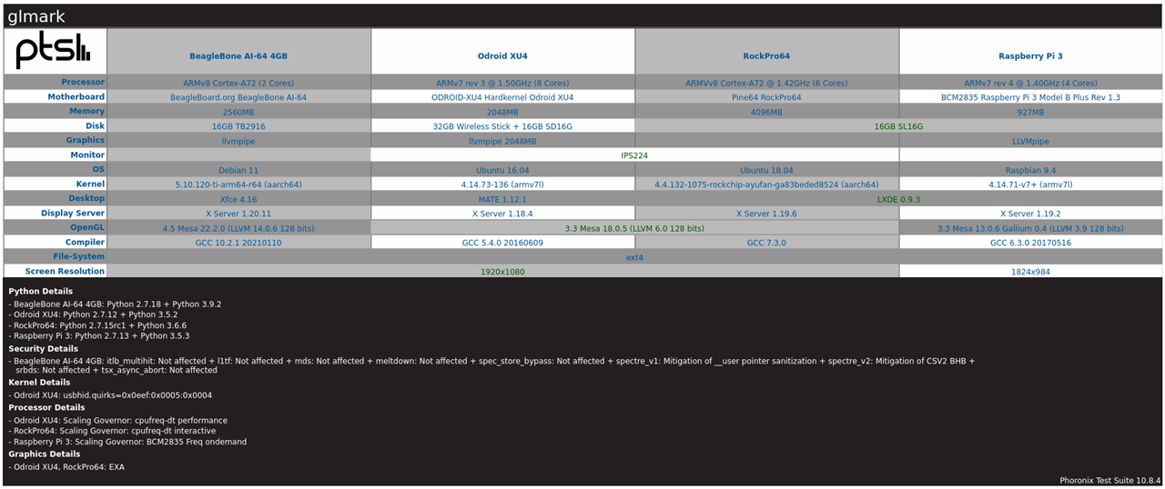


In glxgears the result was around 300 FPS and the results in Speedometer 2.0 was around 17.4 and that is comparable to Raspberry Pi 4b. Below there is also video from performing graphics tests:
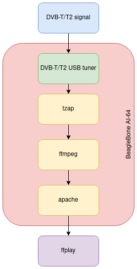
My plan to test these peripherals is based on a small experiment with the creation of a streaming point for SD/HD DVB-T channels via HLS. The basic idea was to use the DVB-T/T2 USB dongle to receive an MUX with channels. Then, with the tzap tool, it should be possible to record audio and video PIDs of interested channels. This recording should be a source for ffmpeg, which should transcode this audio/video data. In the final result, there should be an HLS manifest used by the client application. But to use this, I needed to check first how to access the hardware encoder and decoder with ffmpeg on this platform.
I found the specification of the hardware encoder and decoder and it is the following:
video decoder:
- PowerVR D5520MP2 video processing unit from Imagination Technologies
- Dual-core multi-standard video decoder,
- Decode up 1x4k60/2x4k30/4x1080p60/8x1080p30 streams,
- Formats H.265, H.264, WMV-9, VC1, MPEG2 and others,
- Hardware scaling and rotation,
- Secure playback support
video encoder:
- PowerVR VXE384MP2 video processing unit from Imagination Technologies,
- Dual-core multi-standard video encoder,
- Encode up to 1x1080p60/2x1080p30 streams,
- Formats H.264 MVC/HP/MP/BP, MPEG-4 SP, H.263BP and others,
- Hardware scaling, motion estimation and other accelerations
I found more information about support in the system of hardware decoder and encoder: multimedia
Based on that I know that in system is only supported subset of these codes for:
video decoder: H.264 and HEVC/H.265
video encoder: H.264
This document also describes the software stack for accelerated decoding and encoding. Generally there are two drivers in kernel, one for decoder (vxd-dec.ko) and one for encoder (vxd-enc.ko). Below there is diagram that illustrate that:

Generally, hardware encoder and decoder should be available via the Video4Linux 2 API that is also supported by Ffmpeg.
With that knowledge, I started by testing hardware encoding. Based on initial tests, it seems that it works partially because it is not possible to set the GOP (group of pictures) size and video bitrate. I also tried to change it with v4l2-ctl but it also failed.
With an attempt at hardware accelerated transcoding, I ended up with an oops in the kernel.
Below there is a video of these tests:
So, at this moment, it looks like there are some issues with FFmpeg.
The BeagleBone AI-64 contains 2 x 6-core PRUs, that are fast 200 MHz, 32 bit processors with single-cycle IO access to a number of GPIOs, internal memory or peripherals. On the beagleboard.org there is great PRU cookbook, that describes with examples usage of this units. I have also looked at this blog post: beaglebone-pru, during learning the basics of the PRUs.
I have decided to create a simple example that accesses one of the GPIO pins to generate square wave output. In my example, I used P8_04 as the output pin from PRU with number 0.
The first step was to edit default pinmux in file:
vi /opt/source/dtb-5.10-ti-arm64/src/arm64/k3-j721e-beagleboneai64.dts
# from P8_04_default_pin to P8_04_pruout_pin
After that, it was required to rebuild and install the changed device tree. Below there are images from this process.


Below is the source code of the program and the makefile to build the final binary.
#include <stdint.h>

#define CYCLES_PER_SECOND 200000000 /* PRU has 200 MHz clock */
#define P8_04 (1 << 5) // prg0_pru0_gpo5

volatile register uint32_t __R30;
volatile register uint32_t __R31;

void main(void)
{
	volatile uint32_t gpio;

	gpio = P8_04;
	while (1) {
		__R30 ^= gpio;
		__delay_cycles(CYCLES_PER_SECOND / 2e6);
	}
}
PRU_SWPKG = /usr/lib/ti/pru-software-support-package

CC = clpru
LD = lnkpru
CFLAGS = --include_path=$(PRU_SWPKG)/include \
         --include_path=$(PRU_SWPKG)/include/j721e
LDFLAGS = J721E_PRU0.cmd

all: j7-pru0_0-fw

main.o: main.c
	$(CC) $(CFLAGS) $^ --output_file $@

j7-pru0_0-fw: main.o
	$(LD) $(LDFLAGS) $^ -o $@
The R30 register is responsible for GPIO outputs, so it is required to set a bit in the position corresponding to a given port output. By changing the delay cycle, it is possible to generate a different period of output square wave.The linker command: J721E_PRU0.cmd was taken from the official TI PRU_Halt example, and is required to create the final firmware that PRU can execute. The generated firmware needs to be placed in the /lib/firmware location.
The name of the firmware that PRU will use can be changed by command:
echo "firmware_name" > /sys/class/remoteproc/remoteproc0/firmware
The state of the PRU could be changed by commands:
echo "start" > /sys/class/remoteproc/remoteproc0/state
echo "stop" > /sys/class/remoteproc/remoteproc0/state
Below there is a video of an example test run:
In this chapter, I would like to focus on using this board for accelerated calculations. My plan was to provide an example of the estimation of pi value with the use of the Monte Carlo method. In general, we estimate the value of pi using this method based on the area of a quarter of a circle with radius equal to 1. The area of this quarter is calculated with the usage of the Monte Carlo method based on counting the randomly generated points that fall within the area limited by function and dividing it by the number of tries. Here is a great article that describes it (MC).
My plan was to use of the OpenCL. I found that TI has implementation that uses C66x DSP but unfortunately the SoC used with this board is not ready yet (info). But I found also that GPU PowerVR has support for OpenCL, so I decided to use it. I have used Octave and octave-ocl plugin that allow access the OpenCL. I have created two scripts: one that performs calculations with usage of only the CPU and the second with GPU acceleration. Below there are sources:
% mcPiCPU.m
clear all;
samples = [ 10000; 100000; 250000; 500000; 1000000; 1500000 ];

for i = 1:size(samples,1)
    title(["Number of samples: ", num2str(samples(i,1))]);
    x = single(rand(samples(i,1),1));
    y = single(rand(samples(i,1),1));

    tic;
    r = sqrt(x.^2 + y.^2);
    in = (r <= 1);
    out = (r > 1);
    pi = 4 * sum(in)/samples(i,1);
    exec_time(i,1)=toc;
    hold on;
    plot(x(in),y(in),'r.');
    plot(x(out),y(out),'b.');
    pause(2);
end
format short g;
printf("Execution time [ms]:\n");
exec_time * 1000
% mcPiGPU.m
clear all;
pkg load ocl;

% Carry out a test operation to load the underlying layers that communicate with OpenCL.
tic;
oclTest=gpuArray(single(rand(1000,1)));
oclTestRes = sqrt(oclTest.^2);
clear oclTest oclTestRes;
test_time=toc;

samples = [ 10000; 100000; 250000; 500000; 1000000; 1500000 ];
for i = 1:size(samples,1)
    title(["Number of samples: ", num2str(samples(i,1))]);
    oclX = gpuArray(single(rand(samples(i,1),1)));
    oclY = gpuArray(single(rand(samples(i,1),1)));

    tic;
    oclR = sqrt(oclX.^2 + oclY.^2);
    oclIn = (oclR <= 1);
    oclOut = (oclR > 1);
    oclRes = 4 * sum(oclIn)/samples(i,1);
    exec_time(i,1)=toc;
    pi=gather(oclRes);
    x=gather(oclX);
    y=gather(oclY);
    in=logical(gather(oclIn));
    out=logical(gather(oclOut));
    hold on;
    plot(x(in),y(in),'r.');
    plot(x(out),y(out),'b.');
    pause(2);
end
format short g;
printf("Execution time [ms]:\n");
exec_time * 1000
For both scripts, I have also measured the execution time for comparison. Below is a plot that shows execution time in milliseconds in relation to the size of the random array with points.

We see that there is great improvement for operations for matrices with a size greater than 100,000 points. Below there is a table with the calculated speedup for each matrix size used during calculations.
| Number of samples | CPU [ms] | GPU [ms] | Speedup |
| 10000 | 0,522 | 1,924 | 0,27 |
| 100000 | 3,093 | 1,365 | 2,27 |
| 250000 | 7,152 | 1,448 | 4,94 |
| 500000 | 13,246 | 1,656 | 8,00 |
| 1000000 | 28,784 | 2,038 | 14,12 |
| 1500000 | 39,017 | 13,509 |
2,89 |
Here's a video of the test being run:
So, in this field as well, the BeagleBoard AI-64 performs really well, especially if the C66x DSP could be used in the future.
The BeagleBone AI-64 has support for TRNG built into the kernel driver. The TRNG is exposed to user space via the /dev/hwrng device.
There is also support for AES, DES, and SHA hardware accelerators. I have decided to use them with OpenSSL via the Cryptodev kernel driver. In the below video, there is compilation and usage of the Cryptodev kernel driver, and compilation and usage of OpenSSL with enabled support for this accelerator:
Below is a table with the results of tests for some ciphers with and without hardware acceleration for 8192-byte blocks:
| Cipher | Default [kb/s] | Cryptodev [kb/s] | Speedup |
| sha256 | 948218 | 4687164 | 4,94 |
| sha512 | 264129 | 4016947 | 15,21 |
| aes-256-cbc | 1129698 | 13544106 | 11,99 |
I have decided to run the demo for the image classification that is provided by Texas Instruments. Generally, the demo uses a set of images as input and performs classification of them with usage of the peripherals available in the TDA4VM SoC and presents the results on display. Because I do not have a connected external display, I have modified the output a little to do not use kmssink, because DSS is not available in that situation. Instead, I used filesink and jpegenc to save the images after they were processed. Below there is a data flow for the pipeline for default configuration with kmssink:

Here is also a video from the test run:
In this case, I have run a demo for object detection. By default, the demo is configured to use the V4L2 device as the source and display output on the display via kmssink. Below is the data-flow for this configuration:

I have decided to use video files with a resolution of 360p as sources. I have also changed the output to use the video file. It was also required to modify the gst_wrapper file because there was an error with the bitrate parameter passed to h264_v4l2m2m that was not supported. I have also used the raw h264 output from the decoder for simplicity. I have performed tests for three different video files that are shown in the below video.
This demo has a similar configuration to object detection. Below there is a data flow:

To fit my board configuration with no display connected, I have made here the same changes as for object detection. Below is a video from the test usage:
The BeageBone AI-64 It is a really nice platform for developing artificial intelligence and machine learning solutions. Additionally, with its large number of peripherals and additional subsystems, it is a great platform for a wide range of purposes, from scientific analyses or calculations to designing embedded solutions focused on security. Overall performance is really good, and there are a lot of hardware accelerators that we can use. Thanks to the great documentation and ready-out-of-the-box system, it's like a Swiss Army knife with a wide range of purposes.
Top Comments
Do you have the J721E_PRU0.cmd code?