RoadTest: Maxim Integrated - Industrial Communications with IO-Link Distance Sensor
Author: meera_hussien
Creation date:
Evaluation Type: Development Boards & Tools
Did you receive all parts the manufacturer stated would be included in the package?: True
What other parts do you consider comparable to this product?: From my point of view, i consider this product stands uniquely among other product in a sense that, it has a specific controller board that is quite versatile and moreover this board is being used as the reference for the international standard
What were the biggest problems encountered?: The biggest issue was getting the software license for this kit. But it seems to be quite difficult to get it even-tough has emailed the company few times.
Detailed Review:
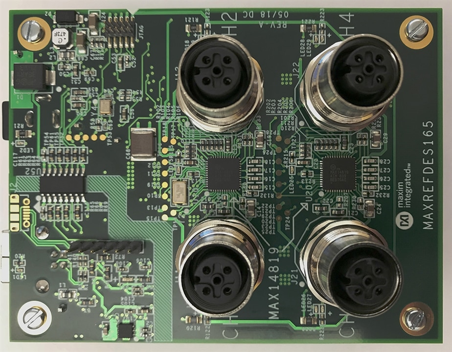
The Maxim IO-Link Distance Sensor Kit consists of MAXREFDES165 and MAXREFDES171. Let's look at the individual device separately. First, we will look at the MAXREFDES165 and followed by MAXREFDES171.
IO-Link is the first open field-bus agnostic, low-cost, point-to-point serial communication protocol for communicating with sensors and actuators. This device is adopted as an international standard (IEC 61139-9), IO-Link standardizes the interoperability of industrial equipment from all over the world. IO-Link can function directly from the PLC or can be converted from all standard field busses through a gateway, quickly making it the de facto standard for universal communication with smart sensors and actuators.
IO-Link is a single-drop digital communication interface (SDCI), which means it supports only one sensor or actuator per port. The three-wire protocol is also backwards compatible with binary sensors and actuators that use standard inputs and outputs. IO-Link device descriptor (IODD) files completely define the device and eliminate manual parameterization.

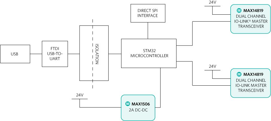
The MAXREFDES165# design utilizes two MAX14819 dual-channel Maxim Integrated IO-Link master transceivers, an on-board digital isolator, the efficient industrial MAX15062AATA+ step-down converter, an FTDI USB-to-SPI interface, and a STMicroelectronics® 32-bit Arm® Cortex®-M4 microcontroller (STM32F4) utilizing TMG TE's IO-Link Device Tool software and TMG TE's IO-Link master stack.
The figure below shows the system block diagram of the MAXREFDES165#.

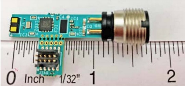
Now let's look at the MAXREFDES171. Advanced factory solutions, such as industry 4.0, require increasing numbers of smart sensors, which are typically controlled using IO-Link for the point-to-point serial communication between the sensor and controller (master). As a leading provider of IO-Link sensor transceiver ICs, Maxim also provides The MAXREFDES171# IO-Link distance sensor consumes minimal power, space and cost, making it a complete solution for distance and proximity sensing in many industrial control and automation applications.

The MAX22513 IO-Link device transceiver is compliant with the IO-Link version 1.1/1.0 physical layer specification. It integrates the high-voltage functions commonly found in industrial sensors, including drivers, a high-efficiency DC-DC buck converter, and two linear regulators all in tiny 4.1mm x 2.1mm WLP. The MAX22513 features extensive integrated protection to ensure robust communication in harsh industrial environments. All four IO-pins (V24, C/Q, DO/DI, and GND) are reverse-voltage and short-circuit protected, and feature integrated ±1kV/500ohm surge protection. This enables a very small PCB area with no required external components (such as a TVS diode). The low-on resistance drivers (C/Q and DO/DI) further reduce power dissipation, thus this reference design consumes minimal power with very low thermal dissipation. Operation is specified for normal 24V supply voltages up to 36V. Transient protection is simplified due to high voltage tolerance (65V absolute maximum rating) in addition to the integrated surge protection.
The DC-DC buck regulator significantly reduces the system power dissipation by dropping from 24V to a lower voltage more efficiently than a linear regulator. The two integrated LDO regulators within MAX22513 allow the 3.3V and 5V rails to be generated, saving external components space. The DC-DC regulator can supply up to 300mA load current, making this transceiver ideal for sensors that require high load current, but at lower voltages than 24V where LDO are inefficient in translating 24V directly to lower voltages.
The MAX22513 features a flexible control interface, allowing control through either an SPI or i2C interface. In this design, we use i2C to reduce the number of pins required by the microcontroller. I2C allows both the MAX22513 and the sensor IC to be on the same bus. I2C (or SPI) interface provides extensive diagnostics (from MAX22513), and a 3-wire UART interface is provided for IO-Link operation.
The MAX32660 is an ultra-low-power, cost-effective, highly integrated microcontroller that combines a flexible and versatile power management unit with the powerful Arm Cortex-M4 with a floating point unit (FPU). The device integrates up to 256KB of flash memory and 96KB of RAM to accommodate application and sensor code. It supports SPI, UART, and I2C communication in a tiny, 1.6mm x 1.6mm, 16 WLP.
The VL53L1X is a TOF, laser-ranging sensor that provides accurate distance sensing ranging up to 400cm. The ranging sensor is programmed with firmware and is controlled by a simple I2C interface that only requires SCL and SDA since the device address is preprogrammed by default to 0x52 (saving address pins). The module does not have a cover for the receiving lens, so care needs to be taken to keep the lens clean, otherwise, distance measurement performance will be impacted. The VL53L1X is in a small, 4.9mm x 2.5mm x 1.6mm module and operates over the -20°C to +85°C temperature range. This is the limiting item for the reference design operating temperature range, as the MAX22513 IO-Link can operate over the -40°C to +125°C temperature range.
The MAXREFDES171# does NOT require external devices such as varistors or TVS diodes for protection due to the integrated surge protection within MAX22513 at the IO-Link interface. This reference design meets both IEC 61000-4-2 (ESD) and IEC 61000-4-4 (EFT) standards. It is designed to meet surge capability (2A at t = 1.25/50us) and has a low clamping voltage of <70V.
The MAXREFDES171# uses an industry-standard M12 connector, allowing a 4-wire or a conventional 3-wire cable to be used, which keeps costs low. The MAXREFDES171# consumes less than 9mA (typ), including the green LED "3.3V alive signal" and the yellow LED that blinks for each distance sensor reading. A red LED indicates if a fault occurs.

Let's watch the unboxing video
You don't have permission to edit metadata of this video.
Since the software is not available to download, there is no further testing that can be done.
Since the software is not available to download, there is no further testing that can be done.
Overall the kit is meant for industrial application with harsh environment. It would have been better if the software is made available for the roadtest at least for trial.