RoadTest: Maxim Integrated - Industrial Communications with IO-Link Distance Sensor
Author: cghaba
Creation date:
Evaluation Type: Development Boards & Tools
Did you receive all parts the manufacturer stated would be included in the package?: True
What other parts do you consider comparable to this product?: STEVAL-IOD04KT1 Smart Sensor Kit, Dual, Io-Link, STEVAL-IOD004V1, Industrial Smart Sensor, STEVAL-IOM001V1 Evaluation Board, L6360 IO-Link Master Transceiver, ST Morpho, For STM32 Nucleo
What were the biggest problems encountered?: Finding detailed documentation for the kits
Detailed Review:
The hardware provided in this roadtest consists of a distance sensor kit, and a IO-Link master kit i.e.:
The two can be tested only working together or if another IO-Link sensor or IO-Link master are available. For me is not the case as this technology, though I heard and read about it, is knew.
Unboxing the kit
The first part of the roadtest was the unboxing of the two kits, inspecting their board and identifying the main parts of the kits. This means, for the sensor kit, identifying the distance sensor device, the microcontroller and the transceiver chip. For the IO-link master the identification will seek for the microcontroller, the tranceiver chips and the other components.


The main components of the distance sensor are the VL53L1 distance sensor, the MAX32660 microcontroller and the MAX22513 IO-Link transceiver.


The main components of the IO-Link Master are 2 dual-channel MAX14819 IO-Link master transceivers, a MAX14931 digital isolator (front side), an STM32F4 Arm Cortex-M4 microcontroller and a FTDI FT2232 USB-to-SPI transceiver and driver (back-side).
The second part of the road test will consist of downloading and installing on the PC the software provided by TMG TE for testing the IO-link master and IO-link devices that are using the TMG TE’s IO-Link master stack. The software can be used to operate the master, see how it identifies devices that are connected to its connectors at power up or which are hot-plugged into its connectors after power up, or how the master detects that one sensor is hot-unplugged from its connectors.
The software can be downloaded from the TMG TE web page in the Download section. The access to the download page is password protected therefore, a password must be requested using a Contact form.
The password and additional information about the products were received after a couple of days.
Installing TMG TE software (IO-Link Device Tool V5.1.1-7475 PE – Setup)
The installation of the software implied the following steps:
- Choosing the language (English)
- Accepting the license agreement
- Selection of the destination folder
- Installation of the CodeMeter runtime (for protection and licensing of the software).
The next step in using the IO-Link Device Tool is discovering the master connected to the PC where the software runs. The MAXREFDES165# IO-Link Master must be powered and connected using the USB cable to the PC. The figure below shows that the master was discovered.

The discovered master appears in the topology window as connected via USB port.

In order to see the information about the master, a IOLM (IO Link Master description can be imported into the software).
The IOLM file can be imported or the description can be retrieved from the manufacturer (TMG TE) web site. The figure bellow
shows the information provided by the IOLM file. The IOLM file is in fact an xml file. As we can see the IOLM provides also
manufacturers' logos and a picture of the device.

The next step is getting the device online in order to discover the sensors attached to the master. The discovery of the slave devices
is initiated by pressing the Check devices button. The figure below shows that the MAXREFDES171# sensor was discovered.

In order for the sensor to be managed by the master, the "Takeover devices into engineering" button must be pressed. After that,
the sensor will appear in the Ports tab of the master.

In order for the master to manage the device, a IODD (IO-Link Device Description) file must be imported into the software.
The IODD file is an xml file that contains all the information the master needs to manage the sensor. By double-clicking the line of the sensor, a new window opens that contains multiple tabs that represent the interface provided
by the software to:
- get information about the sensor,
- display the available parameters of the sensors,
- display data sent by sensor,
- load configuration of the sensor from the sensor memory,
- change the configuration and upload the new configuration into the sensor memory,
- display sensor data in a raw or user-friendly format.
The picture below shows the main information about the sensor such as the vendor, ID, Product Name, description of the sensor, communication speed (in this case COM3), cycle time, and connection information (cable type and connector pins).
A photo of the sensor is also provided.

The process data tab presents the data corresponding to the sensor function. The MAXREFDES171# is a distance sensor based on an optical sensor,
therefore the processing data includes the distance to the detected object from the sensor. The pictures below show the processing data for two positions
of an object in front of the sensor (2116 mm and 60 mm)


Distance sensor Tabs
For each connected sensor, the software provides 7 tabs that allow the user to learn about sensor characteristics, read sensor configuration parameters from sensor memory, change sensor configuration parameters in the sensor memory, and read process data from the sensor.
| {gallery}Distance Sensor Tabs |
|---|
|
Distance Sensor: Common Tab |
|
Distance Sensor. Process Data The Process Data tab shows the values read periodically from the sensor. This depends on the type of sensor. In the case of Distance Sensor, the process data include Distance, Signal rate, Ambient light rate and Range status. The data is according to VL53L1X sensor characteristics (see sensor data sheet at https://www.st.com/resource/en/datasheet/vl53l1x.pdf) |
|
Distance Sensor. Identification Tab The Identification tab shows the identification data such as the Vendor name, Product name, Product ID and others. This data is normally set by the manufacturer of the sensor and are read-only data. There can be also other data that can be used to set different tags for each sensor that would allow to identify sensor location, function or application (I guess these are useful to set when different sensors of the same type are used in the application and we need to identify them easily). |
|
Distance Sensor: Observation Tab The Observation tab displays information that is useful for the sensor maintenance part of the application. We can find here how many hours was operated, how many power cycles were performed, average distance measured and so on. Process data is also displayed in this tab. |
|
Distance Sensor: Parameter Tab The Parameter tab is used to give access to different configuration parameters of the sensor. These parameters can be read only, write only or read/write. The writable parameters can be modified and the new values can be loaded into sensor memory. Also, at any time we can download the actual configuration of the sensor. The sensor parameters and the list of those that can be modified depending on the sensor type. For example, for the distance sensor we can configure if it will work in short or long distance mode. |
|
Distance Sensor: Diagnosis Tab The Diagnosis Tab shows us the status of the sensor. In the picture above we can see that the sensor is OK. |
|
Distance Sensor: Scope Tab The Scope Tab displays the modification of processing data from the sensor. The scope displays the waveform of 4 signals but, unfortunately, there is no information on what is displayed. The user is left to guess. Doing an experiment, resulted that the waveform in red could correspond to the distance measured by the sensor while the blue one, corresponds to detecting the moment an object passes a threshold distance limit, a parameter that can be configured. The main use of this scope is to see that the sensor is working because you can see the waveforms changing according to the measured distance to a moving object. So the sensor is sending data and the master receives it. |
|
Distance Sensor: Generic Tab In the Generic Tab we can see data that is sent from the sensor to the master in raw format. |
|
Distance Sensor: IODD Tab The IODD Tab is the tab that displays information provided by the IODD file in an easy to see and understand format. |
C/Q Signals
Next step in the roadtest of the IO-link distance sensor was to visualize the signals used to communicate between the sensor and the master. The communication is done on the C/Q line. In order to see these signals, the sensor was connected using a fabricated cable (four individual wires) that allowed it to connect the probes of an oscilloscope. The signals are shown below. As IO-link protocol works, there are three types of communication. These can contain process data, on-request data, and system management commands/requests. Process data communication is used to request cyclical process data from the sensor. The other communication types are acyclic and are used for the configuration and maintenance of the sensor or for event-triggered messaging. The waveforms in the picture below correspond to the cyclic process data communication.

In order to understand the signals on C/Q line, I used a logic analyzer. For that, I had to use a voltage divider to adapt the 0-24 V logic signals to 0-5V logic signals that can be input to the logic analyzer.

Trying to decode the signals using the asynchronous serial protocol gives some framing errors. IO-link standard must be consulted in order to understand the protocol used for sensor- master communication.

The next step planned for the Distance Sensor roadtest was to capture the signals on the I2C bus between the optical sensor and the microcontroller. The probes were put in place but, unfortunately, a wrong movement while the sensor was in operation produced probably a short in one of the sensor components.
After that, the sensor could not be found anymore by the master, sensor non-functioning being proven by the fact that the sensor's green led didn't light anymore.
Using the testpoints at the brake away I could see that the 3.3V is missing. Because this voltage is supplied by the MAX22513 IO-Link device transceiver from the 24 V supplied to the sensor via the IO-link connector, I suppose that this chip is the problem. Though it is said that the MAX22513 features extensive integrated protection to ensure robust communication in harsh industrial environments, it seems that it was submitted to something worst. I will see if I can order this chip but replacing it, is for the moment beyond my reach.
... and More
As the title of the road test indicates, I planned in my test to do more than roadtesting the IO-link master and the Distance Sensor. The more in the title refers to another IO-link device that I obtained with the occasion of a giveaway campaign from Maxim Integrated. The device is the MAXREFDES177, i.e. an analog I/O device with IO-link connectivity. The device is based on the MAX2251 IO-link transceiver, Atmel ATSAM microcontroller and the MAX22000 industrial universal analog IO configurable for all common industrial analog input and output, voltage and current ranges (https://www.analog.com/en/design-center/reference-designs/maxrefdes177.html).
Analog I/O device
The device was connected to the IO-link master, and was recognized by it.
If the IODD is not available and not imported in the IO-Link Device Tool software, the software still detects the sensor and is able to receive and display process data.

In this case, only two tabs are available in the software. The Generic tab and the FW Update tab. In the generic tab we can see the process data sent by the connected device. To test the device I have connected a variable voltage supply made with a 9 V battery and a potentiometer, as the device is configured to act like an -10 to 10 V analog input.

Below are two screenshots where we can see that the input values changed when the potentiometer position changed.


In the FW update tab one can import the FW package. A list of vendors are available but I didn't find Maxim Integrated.

After importing the IODD of the device which is available on the device webpage, the seven tabs described for the Distance sensor device were also available.
| {gallery}Analog I/O |
|---|
|
Analog I/O. Common Tab |
|
Analog I/O. Process Data Tab The device is configured as Voltage analog input so in this tab we can see the voltage applied at the device input.. |
|
Analog I/O. Identification Tab |
|
Analog I/O. Observation Tab The tab shows that the device functions as an -10V to 10V analog input |
|
Analog I/O. Parameter Tab This is the tab where we can change the function of the device (analog input or analog output) |
|
Analog I/O. Diagnosis Tab In the diagnosis tab we can see if the device is OK, number of errors (if occurred) and number of hours the device was in operation. |
|
Analog I/O. Scope Tab In the scope we can see the recording of input data when the voltage was modified using the potentiometer. As said before, we can only see the input changed but we cannot see or estimate the values of the input. |
|
Analog I/O. GenericTab |
|
Analog I/O. IODD Tab |
Roadtest Updates
I managed to fix the Distance sensor. As I suspected, the problem was the MAX2251 IO-link transceiver. I replaced it with a new one and now the sensor is working again.
In the meantime, I borrowed an industrial temperature sensor (TA2115) manufactured by IFM and I tested it to see if it can be discovered by the IO-link master and if I can have access to similar data as for the other IO-link devices.
As we can see from the following picture, the temperature sensor comes in a metal case that protects the temperature sensor and the electronic circuitry against potentially dangerous environmental factors (moisture, corrosive agents, electromagnetic disturbances, vibrations, etc). A final product based on the MAXREFDES171 device will need also such a protective case.

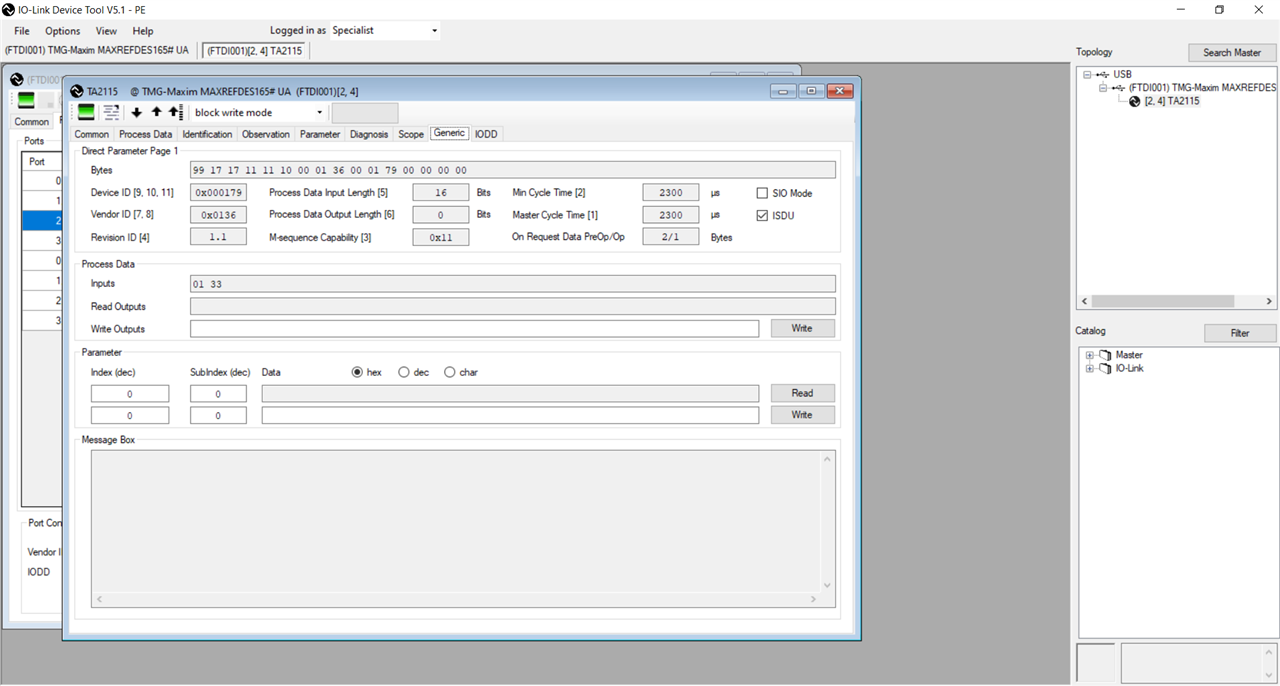
The sensor was connected to the IO-link master and the discovery command was issued in the IO-link Device Tool software. The sensor was discovered and the Generic Tab where the raw data from the sensor can be read. For this sensor the data represents the measured temperature. We can see that without the information from an IODD file, the sensor is marked as unknown though some informatio is extracted from the sensor (type TA2115, ID, version, revision etc).


The IODD file was downloaded from the sensor manufacturer's web page and imported in the IO-link Device Tool software.

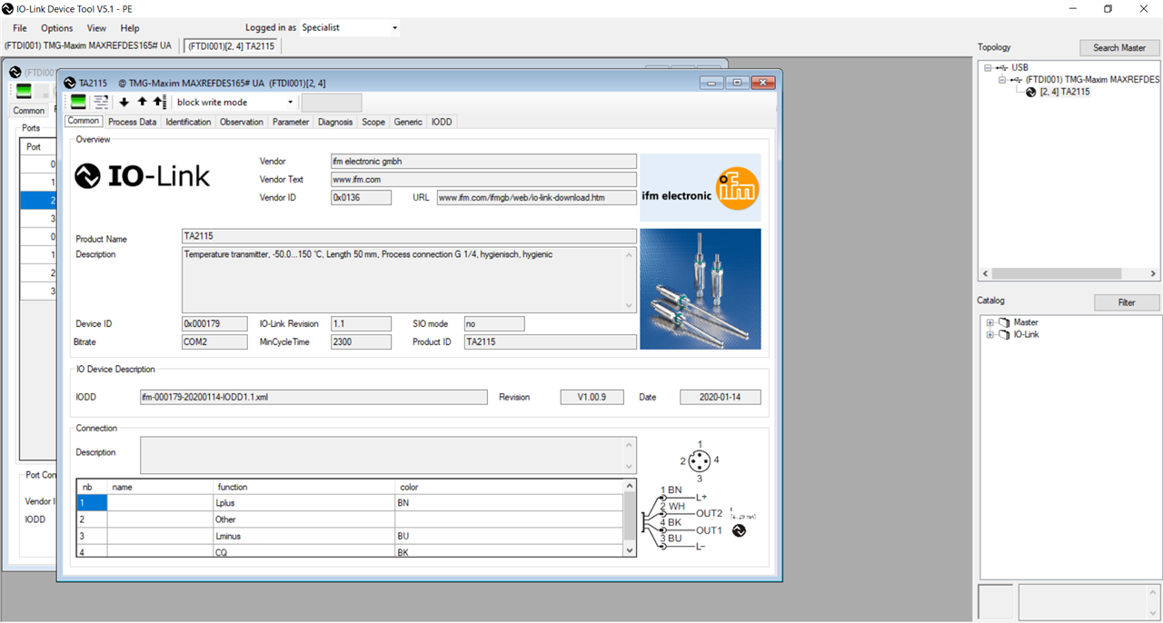
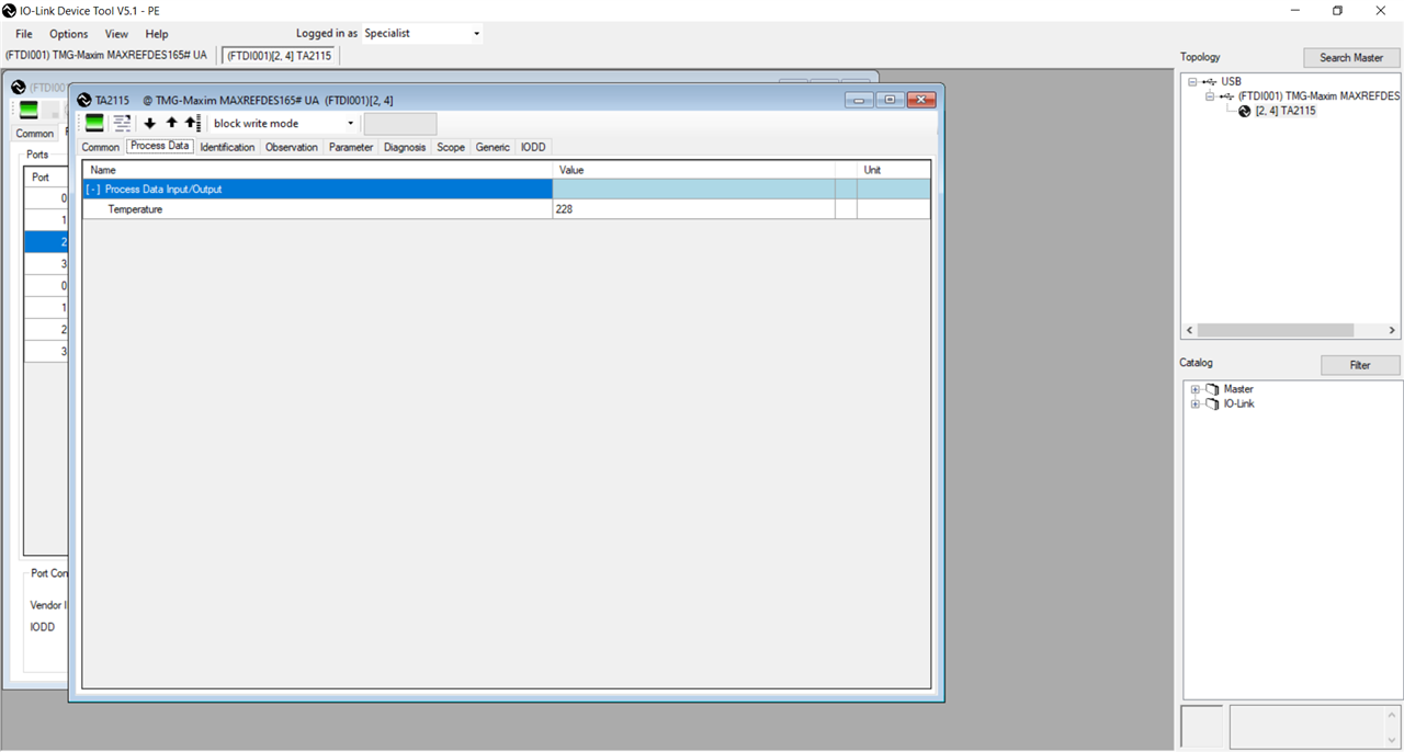
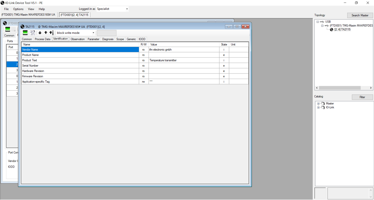
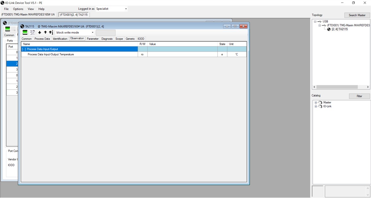
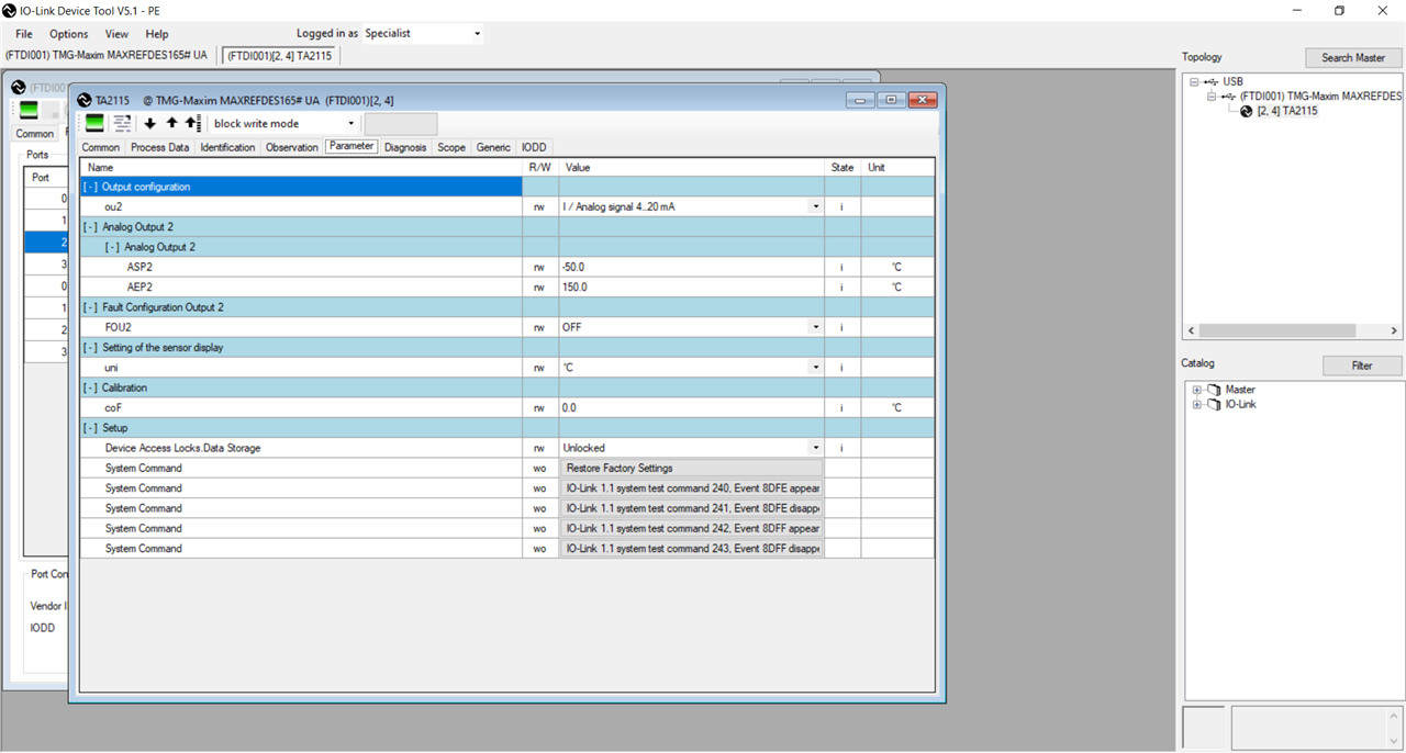
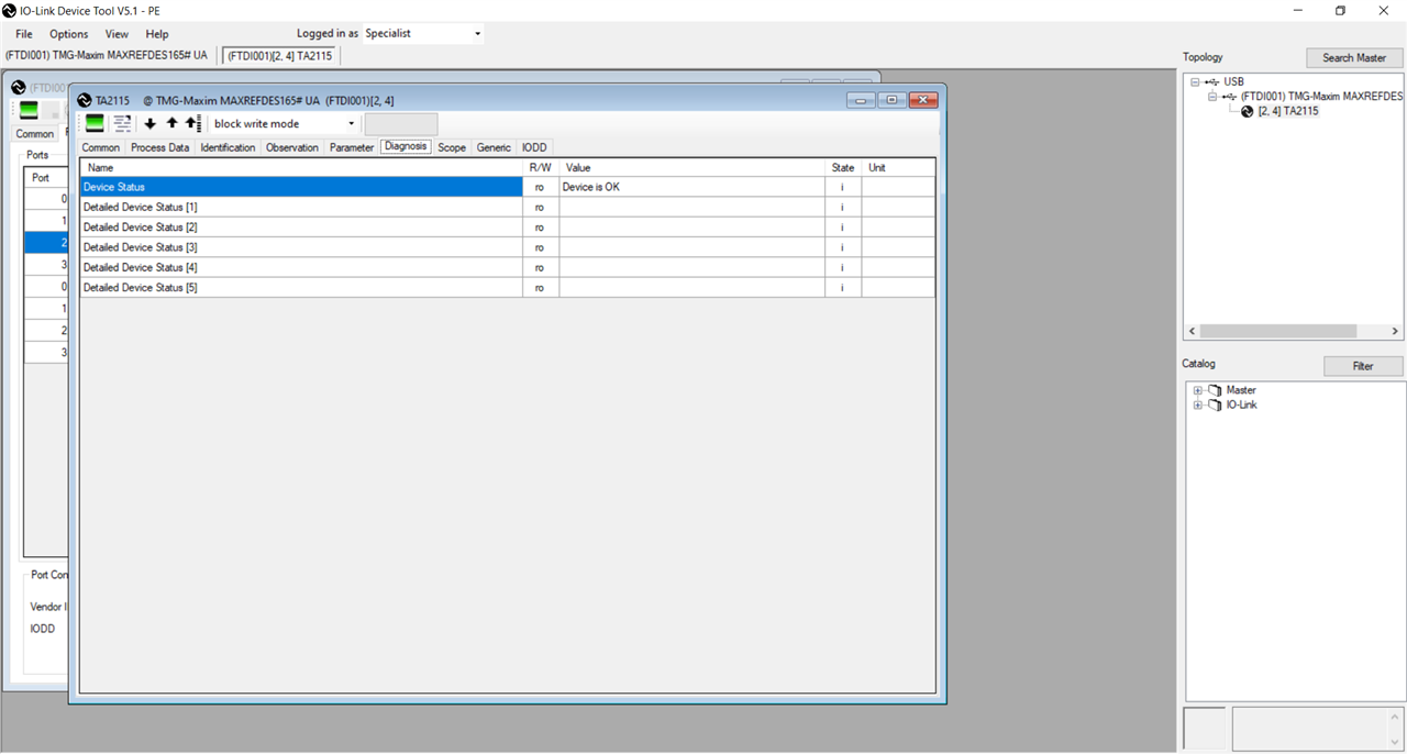
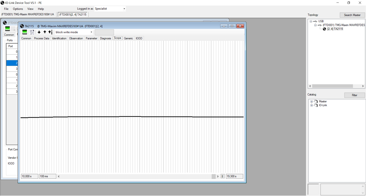
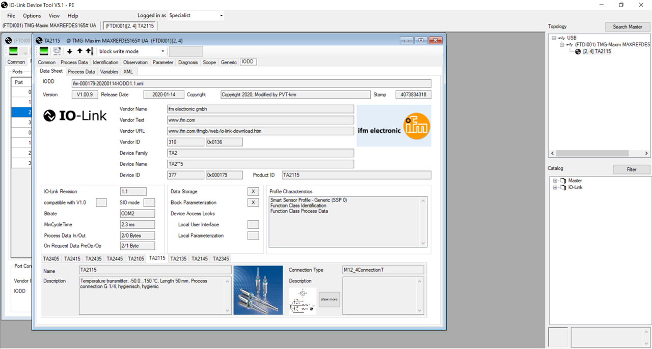
After we have imported the IODD file, the extended set of tabs is available in the IO-link Device Tools software, similar to those for the other IO-link devices tested in this roadtest.
Comparing these tabs with those for the other IO-link devices we can say that this sensor is simpler than the other tested devices.
