RoadTest: AMD Xilinx Kria KV260 Vision AI Starter Kit
Author: digital_pat
Creation date:
Evaluation Type: Development Boards & Tools
Did you receive all parts the manufacturer stated would be included in the package?: True
What other parts do you consider comparable to this product?: Nvidia Jetson Orin
What were the biggest problems encountered?: Tutorial did not have complete information on how to change the part of the design I wanted to change.
Detailed Review:
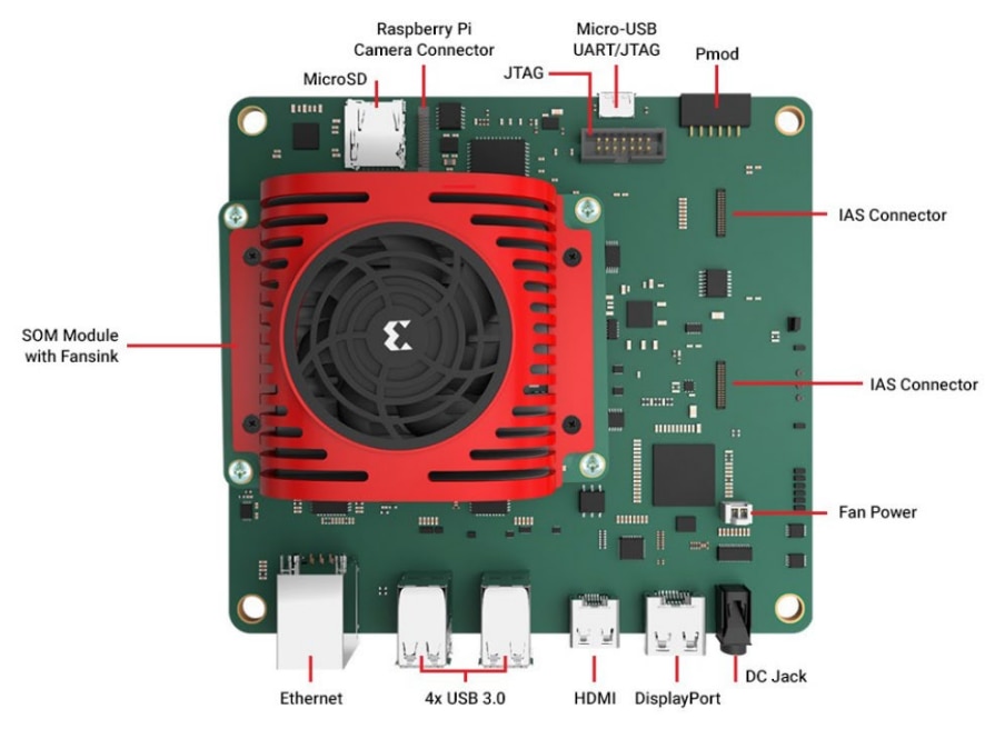
The out of box impression for the Kria KV260 was that I had everything I needed to get the board up and running. Of course my experience included the Kria development kit and the accessory kit. So I had the som module, carrier board, power cord, SD card and cables as shown in the diagram below.

This product is incredibly powerful. The K26 SOM has a quad core A53 with integrated FPGA fabric with ~250,000 logic elements. The processing system connects to the programmable logic through streaming or memory mapped AXI buses. This means that the A53 cores and the FPGA have the same fast access to the memory resources. The FPGA logic is extremely flexible and Xilinx provides 4 flavors of platforms that take advantage of this resource. The user is also allowed to modify the FPGA logic to create a custom platform for a specific need.

Here is a block diagram of the K26SOM with only Connector 1 since Connector 2 is not supported on the KV260 Carrier board. Also the eMMC is removed since this part is not placed on the shipped hardware. This diagram highlights the direct connections between the programmable logic, the processing system, and the system DDR.

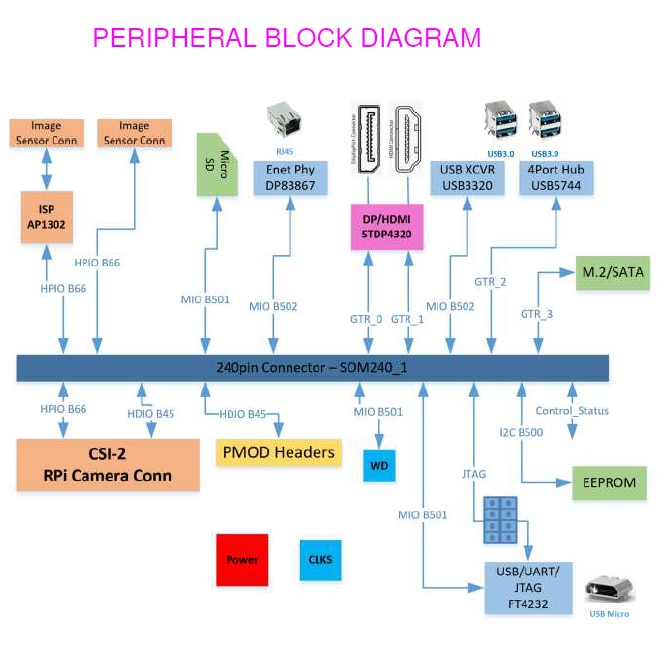
The Next diagram shows the peripherals connected to the SOM on the KV260 Carrier board.
I followed the getting started guide and went with the Ubuntu option. The guide had me install the 22.04 version of Ubuntu. Unfortunately, I was not able to complete the boot. My board had a version of firmware that does not work with this version of Ubuntu. There was a note that pointed me to a wiki to address this issue. I ended up downloading the 21.04r version of Ubuntu to be able to boot; then I could update by following the wiki directions (sudo was needed on Ubuntu). All I had to do was update the firmware and I was able to follow the getting started guide from there. I think there is a better way by accessing the web interface of the update utility, but I ended up downloading many more gigs of images and got it running. I would have preferred clear directions instead of a note pointing to a wiki for the getting started guide.
Here are the general steps I performed to get a clean boot:

I ended up starting with the smartcam example application. The directions to run this application are here. Please note that the directions are version dependent; links to the version are on the left sidebar.
$(lsb_release -cs) stable" | sudo tee /etc/apt/sources.list.d/docker.list > /dev/null
--env="DISPLAY" \
-h "xlnx-docker" \
--env="XDG_SESSION_TYPE" \
--net=host \
--privileged \
--volume="$HOME/.Xauthority:/root/.Xauthority:rw" \
-v /tmp:/tmp \
-v /dev:/dev \
-v /sys:/sys \
-v /etc/vart.conf:/etc/vart.conf \
-v /lib/firmware/xilinx:/lib/firmware/xilinx \
-v /run:/run \
-it xilinx/smartcam:2022.1 bash
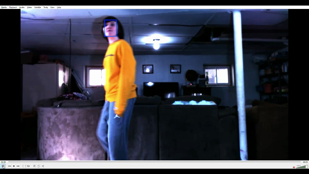
Please note that Ubuntu does not have USB WiFi support for this board. This required being close enough to a router to connect to the internet. Support for USB WiFi can be compiled, but that is not part of the official version. Between the firmware mismatch and the lack of WiFi, it took me about three hours to get the smart cam application up and running. Much of this time was waiting on large images to download.
Next I started research to perform my application development. For this road test my plan is to modify the smart camera application to use an RTSP stream for both input and output. The SOM offers hardware acceleration for the encoding and decoding of video streams. Currently the smart camera application only encodes an RTSP stream for the output. To enable decoding, I figured I need to modify the VCU module in the platform. This is done with the Vivado tool that comes with Xilinx Vitis.
Tool Install:
To install Vitis, you NEED ~300GB of disk space and a computer that can handle some serious number crunching. I installed Vitis 2022.1. The installer is 70GB so it takes a while to download. This is a tool that should be run in a native operating system; No WSL, containers, virtual machines. That is unless you have a system with a ton of resources.
I started with the tutorial to create a platform on the Smart Camera application page. Once I pulled the Git repo, I found a make flow that called a tcl script to build the project. I did have to add a parameter make platforme command to limit the number of threads called JOBS after my terminal window died for lack of memory resources. My system has 16GB of ram with an 11 GB swap. Although this method did work and I was able to open the project in Vivado to modify, I was disappointed that AMD Xilinx did not use the Open Example Project menu option in Vivado. I would second this sentiment for the Vitis project. Here are the steps I performed:
When you open the project in Vivado, the source window The block diagram is listed as a source under a wrapper source file.. You can open the block diagram by double clicking on the block diagram name.
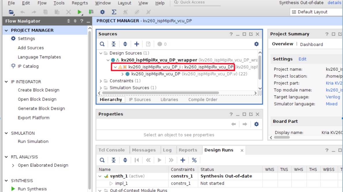
In the block diagram you can see the Zynq UltraScale+ Processor and the elements implemented in the FPGA fabric. One of the modules in the FPGA is the VCU Logic Core. If you double click on that block, a sub-block diagram opens as you can see below.

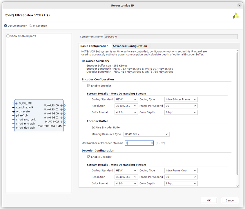
Here you can click on the VCU_0 block to open a window that allows you to modify the IP.
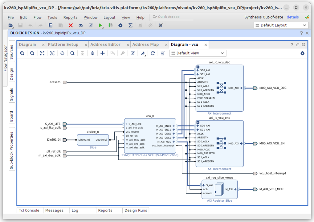
Here I planned to enable both the Encoder and Decoder; only to find that the platform already had what I needed! So I did not have to modify the platform for my current application.
Next I continued the tutorial to create the Vitis project and then Integrate the Accelerator Overlay. Here are the steps:
After completing the steps on the tutorial, I found myself wondering now what. I tried to open the Vitis project and did not have success; I did not feel like I had all that I needed to move forward at this point. Also the smart camera applications source code was nowhere to be found on my system.
So I decided to work on a general Vitis tutorial for the Kria KV260. This tutorial was included on the github document page for the 2021.1 version of the tools and has since been removed. Here you build a Vivado project from scratch. This material talked about the four steps to application development:

I felt the Smart Camera Application tutorials covered much of steps 1-3. The fourth step is the area I am interested in performing. The Vitis tutorial did show me what I was missing with the smart camera project. Please note that I used the 2021.1 version of this tutorial for 2022.1 Vitis install; the latest version of this tutorial has not been updated.
For this step we created a Vivado project for the KRIA KV260 board and then created a block diagram to describe the hardware around the Zynq Ultrascale+ processing system.

I did have to download a BSP for the Kria KV260 board and also the petalinux install to complete the steps.
I got the following warnings when running petalinux-build:
WARNING: Host distribution "ubuntu-22.04" has not been validated with this version of the build system; you may possibly experience unexpected failures. It is recommended that you use a tested distribution.
And
WARNING: Your host glibc version (2.35) is newer than that in uninative (2.34). Disabling uninative so that sstate is not corrupted.
For now I ignored these knowing that I may have issues in the future. I did not experience issues related to this for this evaluation.
The final result showed Test Passed. This proved the flow to create and run an application.
The Smart Camera application has a repo that I can modify to allow a RTSP stream input. This change requires changing the dynamic gstreamer pipeline generation to provide an rtsp_src in main.cpp. As you can see this is not a difficult change, but without a known working process that a modified application will run, I am not comfortable making any changes. So my plan is to build a Vitis project for the kv260_ispMipiRx_vcu_DP Hardware platform. Then import the Smart Camera application project and build. Unfortunately I was not able to complete this before the end of my evaluation period. I am glad that I have a path forward that I am confident that I will see success.
I am generally happy with the hardware platform of this development kit. The ability to run a full Artificial intelligence application in a few hours was impressive. The flexibility to modify the hardware in significant ways is compelling for the advanced user. Xilinx is targeting this product for software developers with little to no experience to FPGA’s. I have found that significant development can be done without this knowledge; at the same time they do offer the ability to utilize the FPGA if you choose. This is impressive since the FPGA offers so much variation in the hardware platform.
Xilinx offers a significant amount of tools to develop very complex artificial intelligence applications. The Vitis AI library allows development with custom integrations for many of the AI open source libraries. The Vitis Video Analytics SDK helps to use the Gstreamer pipelines on the target. The Vivado High Level Synthesis tool helps to push more of the design in the FPGA fabric. This allows the extensible platform to create custom hardware blocks without coding in an HDL language. The vadd example application used this feature. The more general FPGA tools are some of the best in the industry. The FPGA IP blocks that are available allow development without having to create low level blocks. The ability to configure the IP to best match your platform also helps to control the amount of power needed to run; for example you specify the number of video streams in and out of the VCU video codec before the hardware platform is synthesized. This means only the hardware that is needed is included in your design.
My initial experience on this hardware had a Getting Started Guide that did not include everything I needed to know to get up and running. This had a significant impact on the time to run the first app on the hardware. This document is the first impression for a new user, and I think it should be the one and only source of information to get up and running. The document did provide links to other documents, but this required searching the new document for the needed information. I did get everything up and running but it took significantly longer to accomplish.
The product I am trying to make with this hardware is an AI appliance that takes data from my network camera and streams it to my Doorbell system. Since this looked very similar to the Smart Camera Application, I started with the tutorials associated with that application. I found these tutorials to be insufficient to get a full understanding of the process needed to build an application on a custom platform. First the example applications did not use the example store that is part of Vivado and Vitis; instead a make flow called a TCL script to create a project and implement the IP. This did not help the user see the processes they will need to know to do this themselves. The Vivado project was complete and easily understood, but I have experience with this tool. The Vitis project was NOT clear after running the make flow to create it. When I tried to use the Vitis project it felt like I was missing important parts of my platform (BOOT, ROOT_FS, SD-CARD).
I was able to get an understanding of the application development process with a tutorial for creating a custom hardware platform and a Vitis application on top of it. This forced me to load Petalinux, Xilinx’s custom version of Linux. Through this tutorial I was able to find a path that I know will produce my application. That being said, I have not actually completed the development of my application. It took significantly longer to find important information due to holes in the example design tutorials. All of the needed information was available, but having to search for it took way too long.
I do think much of the issues I had with the tutorials and documentation were due to a new focus on using Ubuntu when the official version of Ubuntu was released. I do like the idea of running a familiar Linux distribution, but not at the cost of having to develop apps that only run in docker containers that have to be built on the target. Petalinux is a mature distribution that has built in support for the features of this device. By having full control of the Linux build, it is easy to insert your app on an extremely dynamic hardware platform. It would be nice to see two flavors of the example designs, one for Ubuntu and one for Petalinux.
A lesson learned from this review was that my home equipment was not up to the full task. The demands on the hardware to run the development tools were significant. You needed +300GB of hard disk space and more than 16 GB of memory on a computer running the “right” version of Ubuntu. I was able to get the tools to run, but I had to override the defaults for the number of Jobs. This was not straightforward in the Vitis tool.
My plan for this review was to compare the Kria KV260 to the Jetson Nano. Since the Nano did not have good performance with video streaming in and out, I thought it would be good to highlight the capabilities of this device. Unfortunately I did not get that feature working on the Kria yet. I will say the Nano example designs were complete and the author, Rusty, was very visible to ask directly or through the forums.
Note: Some images came from Xilinx Documentation and were used to promote a Xilinx product.