RoadTest: Sign Up to Roadtest the ADI ADALM2000 Data Acquisition Module
Author: kmikemoo
Creation date:
Evaluation Type: Test Equipment
Did you receive all parts the manufacturer stated would be included in the package?: True
What other parts do you consider comparable to this product?: None. Compared ADALM2000's signal generator to generic DDS Dual-channel Arbitrary Waveform Generator 200MSa/s. Compared ADALM2000's oscilloscope to Multicomp Pro MP720016 USB Oscilloscope.
What were the biggest problems encountered?: The performance of USB instruments are very dependent on the computer they are plugged into. If a potential student has a lower end laptop with minimal RAM, they will have a poor experience (a lot of "Not Responding" errors). Perhaps have a Scopy Lite version for these computers.
Detailed Review:
Introduction
As an electronics hobbyist, I was very interested in this RoadTest. The ADALM2000 is not only a number of instruments, but it's also supported by a full curriculum of learning activities and experiments. My limited electronics knowledge is dated at best. This device is billed as an ADvanced Active Learning Module. Challenge accepted. Teach me.
The stated RoadTest goals were to test the out-of-box experience with the product and to experiment with its capabilities. An optional goal was to produce an unboxing video. My RoadTest plan was to do an unboxing and getting started video and to compare the ADALM2000's signal generator and oscilloscope functions to the stand-alone instruments that I have. From there, I planned to complete the Electronics I training plan that Analog Devices has for the ADALM2000. I also planned to finish the RoadTest by building and testing low-pass and band-pass filters for 3.5MHz, 7MHz and 14MHz (Amateur Radio bands for 80m, 40m and 20m).
Getting Started
The unboxing and getting started video is a little more than 12 minutes long but it goes from installing the software to making measurements - and comparing the ADALM2000 to the stand-alone signal generator and oscilloscope.
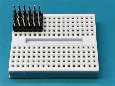
For those that cannot watch the video, getting started is really simple. I did the Windows install since I have Windows laptops. Using the provided USB cable, plug the ADALM2000 into the computer. Initially, it looks like a USB stick. Select the info.html file and it will load a local webpage with installation instructions. Install the three files it directs you to and reboot. You are ready to start hands-on learning. You will need to provide your own breadboard. I found the most convenient breadboard setup was to use four of the extra-long male headers provided in the box and arrange them as pictured below. The remaining open hole allows for a male jumper to expand the buss if you need it.
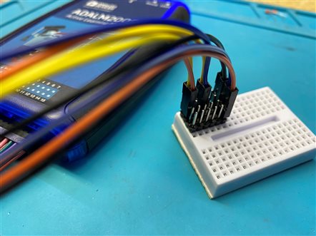
To try the instrument out, connect one of the Ground wires to one of the male headers to create a Ground buss. I chose the right most row. Connect Analog Output 1 (Signal Generator Channel 1) to Analog Input 1, Positive (Oscilloscope Channel 1). Connect Analog Input 1, Negative to Ground. Connect Analog Output 2 (Signal Generator Channel 2) to Analog Input 2, Positive (Oscilloscope Channel 2). Connect Analog Input 2, Negative to Ground. See picture above.

Now launch the Scopy software you installed earlier. Scopy is the ADALM2000's interface software. It has a demonstration mode that allows you to try out a mock ADALM2000 without actually owning the device. Oddly enough, it behaves exactly like the real instrument in that if you have a bunch of windows open on the computer running Scopy... you can lock the software up to where you have to close the application and re-launch it. Not always... but sometimes. This proved to be true on an Intel I3, I5 and I7 laptop. The system is most stable when the ADALM2000 is the only user process going on. You do have to remember to RUN both instruments (the signal generator and the oscilloscope). This can be done by selecting the [RUN] button for each instrument or by clicking on the small white square next to the instrument name on the left instrument pane. The white square will turn to a green triangle (pointing right) when the instrument is running.
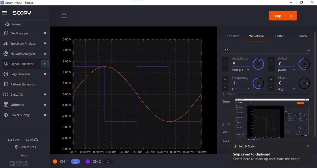
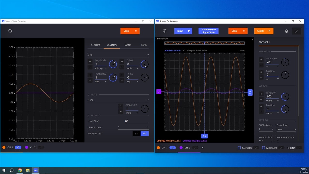
The Signal Generator output is below. Channel 1 is a 1kHz sine wave. Channel 2 is a 2kHz square wave.
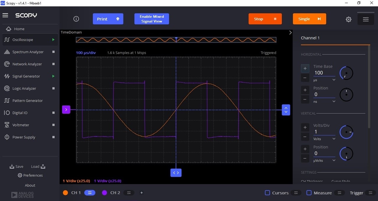
The Oscilloscope display of the Signal Generator output is below.
A SUPER COOL feature of Scopy is that you can detach and move the instrument windows. Just double click on the instrument name and it pops out a separate window. The two windows below were placed on a second monitor for the screen shot.
An even cooler feature is the zoom feature. Just draw the box and the software zooms to the box. You can zoom within the zoom. Clicking the right mouse button backs you out to each successive zoom level.
While getting started, I only used two of the nine instruments. The ADALM2000 has seven more, plus two timing triggers and bus analyzers. I will not be testing out all of the instruments in this RoadTest but I plan to use the Oscilloscope, Signal Generator, Network Analyzer and Power Supply quite a bit.
Oscilloscope – Two-channel oscilloscope with differential inputs
Spectrum Analyzer – power spectrum and spectral measurements (noise floor, SFDR, SNR, THD, etc.)
Network Analyzer – Bode, Nyquist, Nichols transfer diagrams of a circuit. Range: 1Hz to 10MHz
Signal Generator – Two-channel arbitrary function generator
Logic Analyzer – 16-channel digital logic analyzer (3.3V CMOS and 1.8V or 5V tolerant, 100MS/s)
Pattern Generator – 16-channel pattern generator (3.3V CMOS, 100MS/s)
Digital I/O – 16-channel virtual digital I/O
Voltmeter – Two-channel voltmeter (AC, DC, ±25V)
Power Supply – Two programmable power supplies (0…+5V , 0…-5V)
Two input/output digital trigger signals for linking multiple instruments (3.3V CMOS)
Digital Bus Analyzers (SPI, I²C, UART, Parallel)
In the Getting Started video, I also connected the output of a stand-alone signal generator and measured the output with the ADALM2000. I also used the MulticompPRO MP720016 USB Oscilloscope to measure the ADALM2000's signal generator output. Each instrument performed on par with its counterpart. Given the different hook-up arrangements, I did not worry about minor variations in readings.
Getting Started Summary
This is a powerful tool. I found the initial setup very well documented. There are numerous documents and videos online to walk you through the process. The ADALM2000 is also fairly intuitive - although you could miss some really nice features if you don't read the wikis or watch some of the videos. I was able to figure out how to decrease the number of samples in a sweep of frequencies without reading anything. Network Analyzer. Page down. Samples Count. Done. Many times, the next cool feature was discovered by scrolling down the window just a bit.
Overall, the out-of-the-box experience was excellent. HOWEVER... it's a USB instrument. It relies on the computer to do the processing. If you try to multitask too much, you will get a (Not responding) error - even on the Demo. The more powerful the computer, the better the experience. I improved my experience by upgrading the RAM on the computer I chose to use. In the end, I chose to only run Scopy on that computer and I used a second computer (old 32-bit laptop) for the internet and webpages. I even gave up on the second monitor. While the computer is a first generation I-7 processor, it's still a decent computer.
Getting Started Learning
As stated above, the ADALM2000 is an ADvanced Active Learning Module and the module and the curriculum build around it work incredibly well. Initially, I questioned the "ADvanced" in the name, but the curriculum is not really for the electronics beginner. The ADALM labs can supplement a traditional electronics course or more formal learning. The labs do an amazing job of demonstrating - in real life - circuit characteristics. Some parts of the labs force you to do the math that supports building the circuit to get the desired outcome - and then the instrument shows you the output of what you built. It is NOT a simulator. You really have to build the circuit. When you don't get the expected outcome (the labs guide you on what the outcome should look like), you get to pour over the circuit to see where you went wrong. <- Also a very useful skill.
The Electronics I curriculum that I chose for this RoadTest consisted of the following labs.
The individual labs demonstrate the concept they are showing very well - even if the real life circuit was a bit off from the simulation output. Knowing that this is a time proven curriculum also proved useful as I built the circuits incorrectly more than once and had to figure out what I did wrong. I had the expectation that at least one of the labs would seem much cooler than the rest, but that didn't happen. They taught the concept they were created to share and I just moved on to the next lab. Looking back, that is exactly what is supposed to happen. That is not to say that it wasn't thrilling each time the circuit ran as it was supposed to. It was awesome. MANY times I caught myself thinking "I wish I had this when I was going though school." - while just staring in mild amazement at the output. I will also add... there was way more content in the curriculum than I thought. Couple that with the ability to swap out components to see how it affects the circuit... wonderful rabbit holes.
RF Filters
I would be lying to say that I wasn't excited to get to this part of the RoadTest. However... once again, I fell into the trap of tweaking the circuits. I kept reminding myself, "It's about the instrument, not the experiment." I also discovered another cool feature. When I ran a sweep with the Network Analyzer, if I had not set the limits correctly, I could adjust them afterwards and still see the data. I can't do that on my NanoVNA.
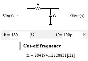
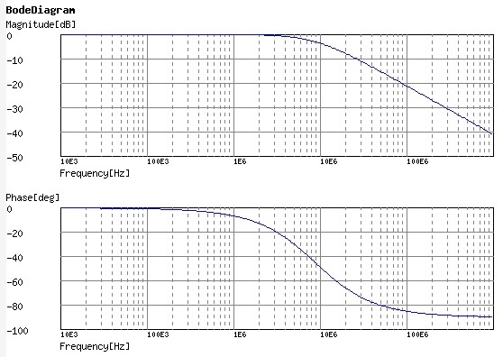
The first filter was a 3.5MHz lowpass filter. My band of interest is actually 3.5MHz to 4.0MHz so I set the rolloff frequency around 4.5MHz. I played with a few mutli-stage filters before settling on a simple RC lowpass circuit. I used http://sim.okawa-denshi.jp/en/Fkeisan.htm as my online calculator.
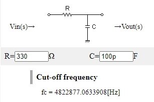
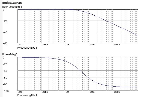
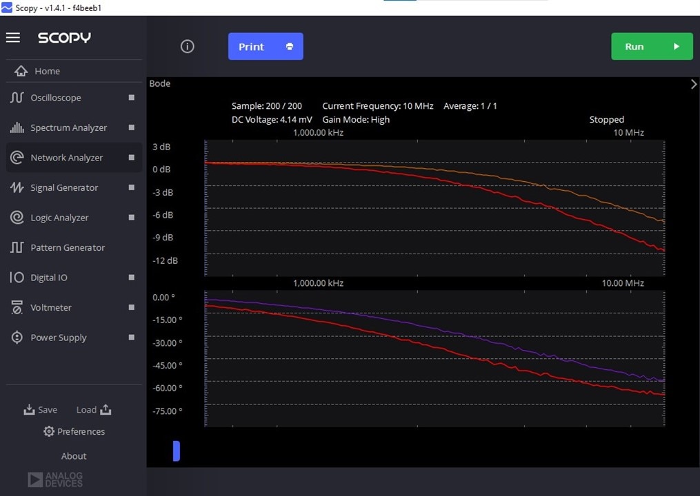
I assembled the circuit and ran the sweep. The results are below. The red trace is the circuit with the 100pF capacitor. The orange trace uses a 47pF capacitor because a 5dB loss at the final desired frequency seemed a bit much.
I was able to get better results with a bandpass filter - but that was primarily through experimentation.
The result from the assembled circuit is below. The red trace was with the original calculated components and the orange trace was the trace after swapping a few components. The actual ideal capacitance to get the bandpass centered on 3.75MHz proved to be 122pF (determined by successive substitution). This response was way more in line with what I wanted from a filter and far better than just what the RC lowpass filter yielded. I also discovered a 14MHz bandstop filter. The component that allowed such a change in the trace wound up being the parallel resistor. Go figure.

On to the 7MHz filter. Seeing the sweep in real life was a bit disappointing. The RC filter plot looked promising.
What i measured was...
2dB+ loss at my target frequency and essentially a flat curve. "FOCUS, Michael. It's about the instrument."
The Bode plots and the circuit simulations can cause us to have unrealistic expectations. But the real circuit... is real. The response is what you measure. The ADALM2000 is doing its job. I'm learning.
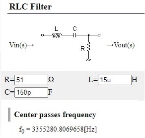
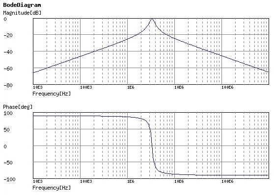
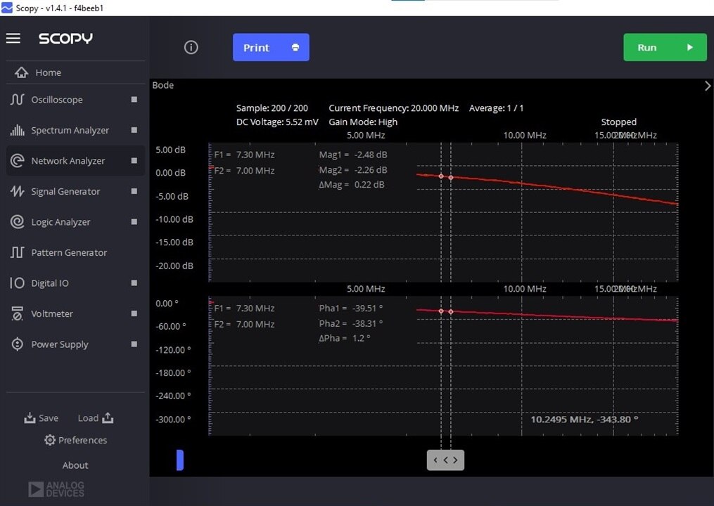
For the 7MHz bandpass filter, the results were more promising.

I assembled the circuit and ran the sweep.
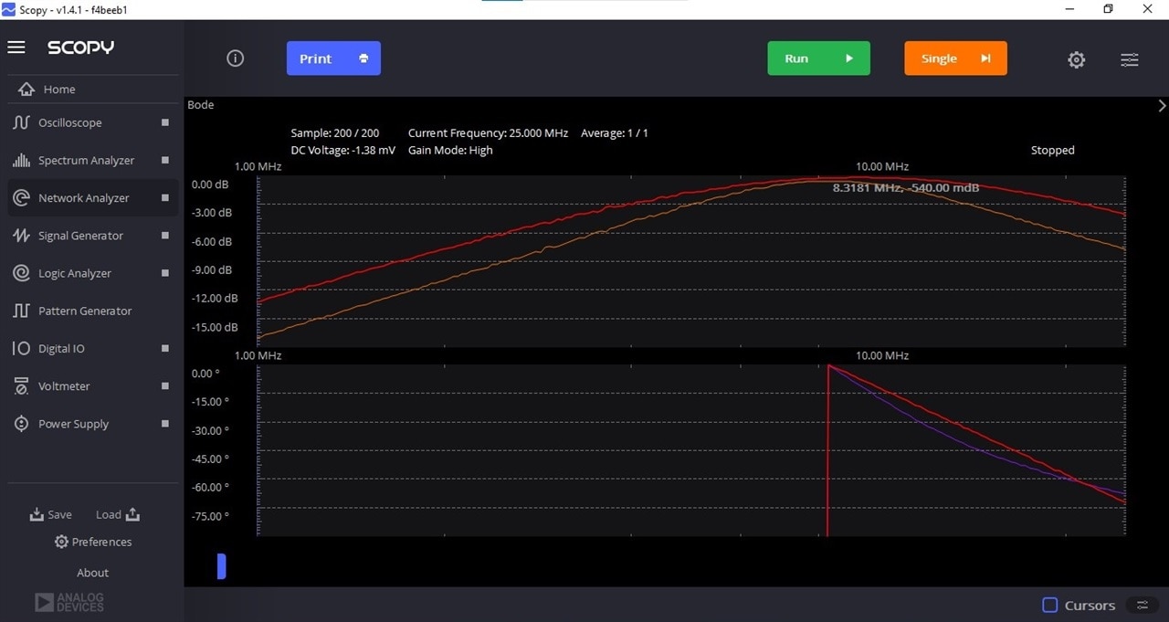
The red trace has the 82Ω resistor. The orange trace is with a 51Ω resistor - that more closely represents coaxial cable and an amateur radio antenna.
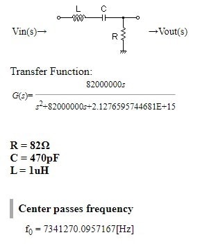
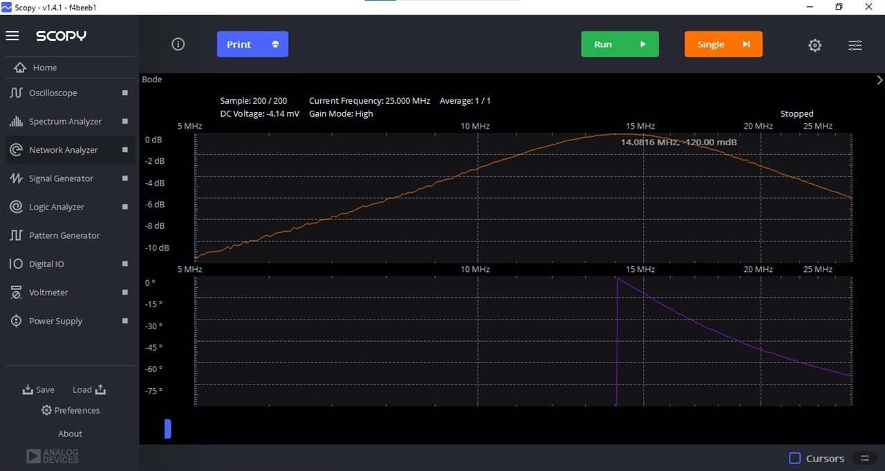
The next endeavor was 14MHz. Once again, the simple lowpass filters were underwhelming. The RC filter was unimpressive so I tried a LR filter. Also underwhelming.
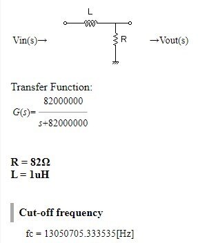
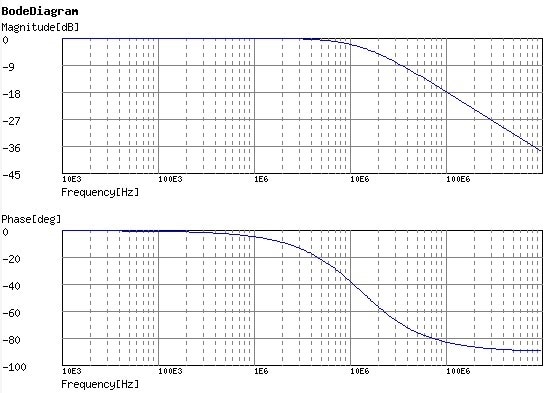
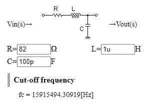
The red trace is what I measured for the LR filter. I opted to try a LCR lowpass filter. This is the orange trace.

The LCR filter is better in the frequency range of interest (14.0MHz to 14.35MHz). It has better low end pass through and high end rolloff, The resultant frequencies are off a bit from the calculated values, but that is fine as the calculated rollofff frequency was too low anyway. The LCR calculated values and traces are below.
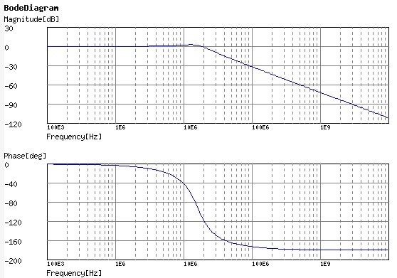
Once again, the bandpass filter proved to be the better option.
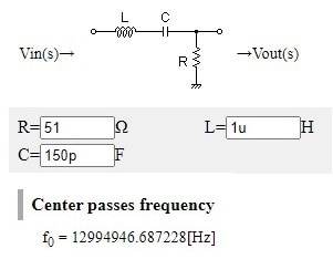

The measured curve is flatter than the calculated response, but there is still around 5dB attenuation at the 1/2x frequency and the 2x frequency points.
While doing these experiments, I discovered yet another cool feature of the Scopy software - averaging. You can set the Network Analyzer to average x readings to smooth out fluctuations in readings. The more I use the ADALM2000, the more I like it.
Conclusion
As stated before, throughout this RoadTest, I had to continually remind myself “It’s not about the experiment. It’s about the instrument.” I think that speaks highly of the usability of the ADALM2000. I wasn’t focused on how to get the readings. I was just able to take them. I found the Scopy interface intuitive and well laid out; very usable. There are also numerous features that make the instrument so user friendly. Zoom, Averaging and rescaling after the capture are my current favorites. I'm sure that I will discover a few more through use.
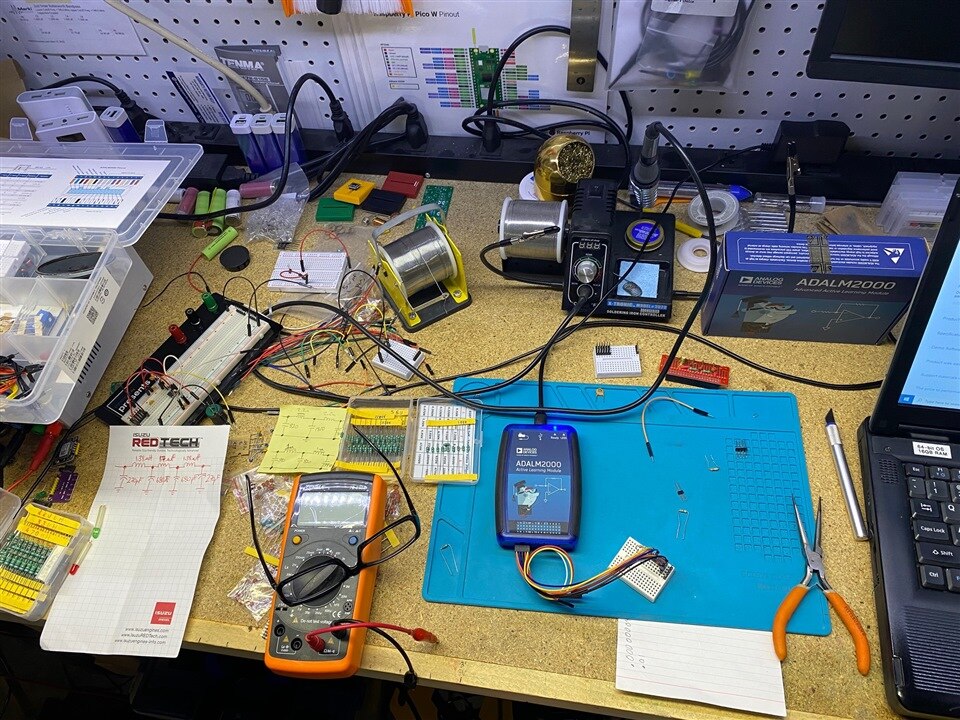 I have a huge appreciation for the space the ADALM2000 does NOT take up on the test bench. Not having to make space for the power supply, signal generator and oscilloscope was fantastic. Of course, I filled that space with too many component bins, but it was nice to have that option. I also didn’t have to take an instrument away to make space for another instrument when I shifted from oscilloscope to network analyzer. I didn’t even have to rewire anything. ... while the workbench is messy, LOOK AT ALL THAT SPACE!!! That, in and of itself, should get you thinking.
I think everyone who is studying electronics should have an ADALM2000. Even with the recommended parts kit, the cost is about half the cost of a class at my local technical college. Back in the day, I’m confident that I paid that much just for books for a single class. We all have an appreciation of something measured and not just simulated. It’s hard to argue with real.
The ADALM2000 is also perfect for the person going back to school. The ability to do labs at home… priceless, especially for the student with a young family that needs you at home also. That is not the only case. It’s just what my situation was when I went back to school. For the hobbyist, it’s every instrument. Sure, you’ll eventually buy stand-alone instruments, but for now, you have what you need to progress. I also plan to use the ADALM2000 in teaching my technicians - specifically about an SCR controlled bridge rectifier. Again, it's hard to argue with real.
My out-of-the-box experience with the ADALM2000 was excellent. I did ding the "Product Performed to Expectations" one half star because using the window pop-out feature on a second monitor caused (Not responding) on even my newest, fastest I-7 laptop (my work laptop). In its defense, it was able to recover - sometimes. The Demo Software got dinged a full star because I shouldn't be able to lock up a Demo - but I did (multiple times). I do give the Demo credit for behaving just like a real instrument.
Overall, the ADALM2000 is worth the investment for electronics students and hobbyists. The instrument itself is powerful and incredibly versatile. The supporting curriculums are well laid out and do a great job covering the teaching points. Having used this system, if I had (hopefully have) a loved one in my life that was taking electronics... I would buy them the ADALM2000 and the parts kit. For the electronics "professional"... you cannot beat the size. Again, look at all the space left on the workbench.
I would like to thank element14 and Analog Devices for the opportunity to RoadTest the ADALM2000. I plan to start on the Electronics II curriculum - because there are still a lot of components in the parts kit that I haven't played with yet. It really is an awesome instrument.


