RoadTest: Enroll to Review the STM32U5A9J-DK Discovery Kit with Embedded Display
Author: navadeepganeshu
Creation date:
Evaluation Type: Development Boards & Tools
Did you receive all parts the manufacturer stated would be included in the package?: True
What other parts do you consider comparable to this product?: STM32H7 kits with embedded display, Nextion TFT displays
What were the biggest problems encountered?: Integration with TouchGFX and interoperability with STMCube and TouchGFX
Detailed Review:
The STM32U5 kit is a particularly interesting one because of its hybrid capabilities with low-power and high-performance. The embedded display, tight integration with TouchGFX, low power features are what attracted me to RoadTest this kit. The first thing I do before signing up for any RoadTest is to look at the documentation and extent of support available. Although no much open source projects or discission have been there in ST Community regarding this U5-DK, the STs training document and slides were exhaustive. This helped me structure the RoadTest plan and phases of experimentation to put up an application. Throughout the review, we'll delve into the eye-catching features and build some small demo projects. I have looked at the TouchGFX usage standalone in the designer app(although had issues in integrating with cubeIDE), RTC peripheral operation and interfacing the onboard ToF sensor to build a desk pomodoro clock demo, then the low power features using LPBAM( low-power background autonomous mode)
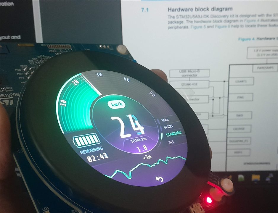
The kit arrived well packaged as always. ST's packaging turned more to more of an eco-friendly look probably advocating sustainability. This includes a thanking note and user manual with the board itself on a ESD safe cover.


| {gallery}Development Kit Board Gallery |
|---|
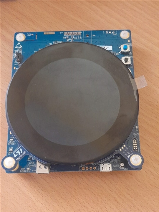
IMAGE TITLE: THEN IMAGE DESCRIPTION |
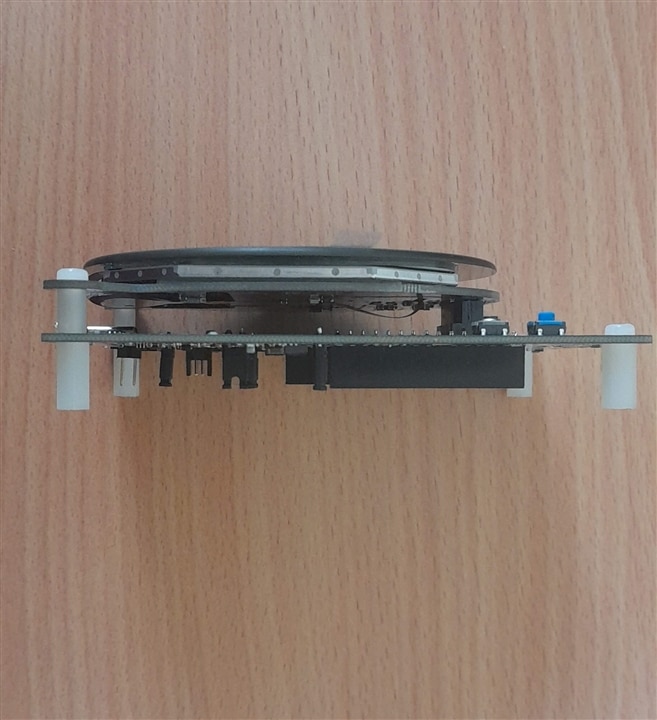
IMAGE TITLE: THEN IMAGE DESCRIPTION |
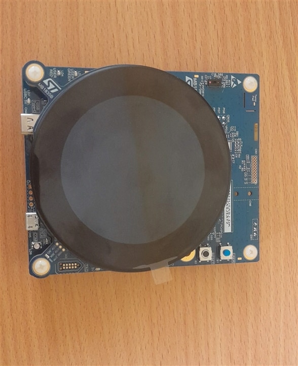
IMAGE TITLE: THEN IMAGE DESCRIPTION |

IMAGE TITLE: THEN IMAGE DESCRIPTION |
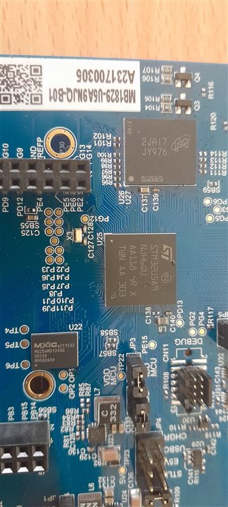
IMAGE TITLE: THEN IMAGE DESCRIPTION |
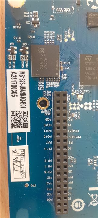
IMAGE TITLE: THEN IMAGE DESCRIPTION |
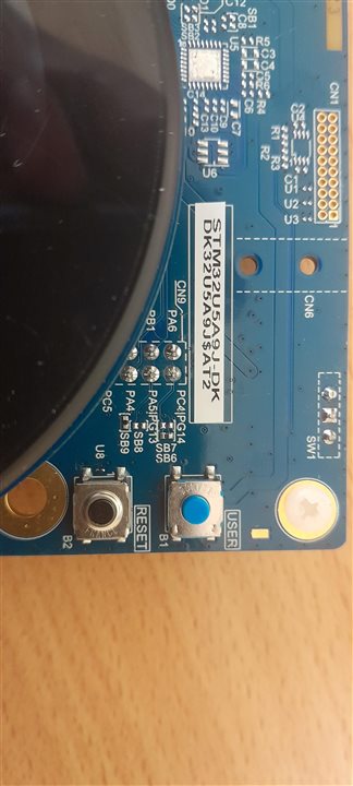
IMAGE TITLE: THEN IMAGE DESCRIPTION |
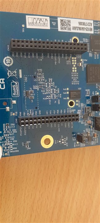
IMAGE TITLE: THEN IMAGE DESCRIPTION |
The board comes with a supercool out of the box demo program having multi-application examples ranging from electric-vehicle dashboard to clock displays. The display quality and touch response looks amazing in these examples.
You don't have permission to edit metadata of this video.
LPBAM = Low Power Background Autonomous Mode
LPBAM is an operating mode that allows peripherals to be functional and autonomous independently from power modes and without any software running.
It is performed thanks to a dedicated hardware subsystem embedded in the STM32U5 microcontroller.
It's a subsystem mechanism that makes use of DMA to configure features for several pheriperals and transfer data
An LPBAM task can operate independently of device power mode (STOP 0/1/2) and without any software running on CPU thanks to DMA data transactions.
Asyncronous events/interrupts can be programmed to wake up the system thanks to autonomous peripherals (Not all peripheral)
Automatic start of the peripheral thanks to the hardware synchronous or asynchronous triggers (automated peripheral kernel clock switching)
This being one of the selling features of this board, I installed the TouchGFX Designer App. The application has this discovery board in selection and can be instantiated with FreeRTOS or Azure RTOS. This has a similar code generation method using CubeMX and inclusion of all TouchGFX wares happens in that stage. With the STLink programmer app installed in the root location as required by the TouchGFX, the design is ready on screen as breeze. The link age between the design and code happens once the project is imported to CubeIDE. Navigating to the TouchGFX folder, certain .cpp files have the initialization of the instances defined in the designer app and the functions have to be exploded to apply an action. Say for example to toggle a GPIO pin while a graphical button is pressed or simply increment a number displayed on the screen!
Official documentation on the site (https://support.touchgfx.com/docs/tutorials/tutorial-02) helped getting the first example up and running.


The project import part was a bit tricky. All worked smoothly with running the application from TouchGFX designer app, but there are multiple ways of importing the generated project files to CubeIDE. It can be right-away done by clicking on the .project/.cproject file in the directory or using the open existing project option in the file menu. Ideally, either of them should work the same, but I had an issue where the earlier version of FreeRTOS would get included in the project after import and had to manually upgrade the version to 1.1.0 (shown in the above image). This was pointing to errors in the freertos heap.
After the upgrade the project was built but ceased to run with the execution going into a hardfault handler in the FreeRTOS task scheduling process although the same was running perfectly while uploading the code via TouchGFX run button. Next I bet on the Azure RTOS which seemed to work fine in the initial building and upload process after importing to CubeIDE but the graphics didn't appear well while the upload is done through CubeIDE. The below image shows the same program uploaded via TouchGFX designer vs CubeIDE after importing the same.
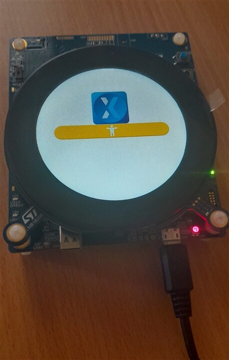
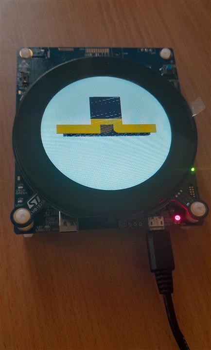
Background: I've followed the method mentioned in this video, Jan's blog and and also a method of creating new TouchGFX project in CubeIDE from scratch.
At this point I did not have enough time to workaround this and referring the community forums only gave generic solutions or pointed in a different trajectory. I'd be curious to know what other RoadTester's view is regarding this and if it has worked out for them!
The STM32U5 BSP provides extensive set of examples for several peripherals and initially, I used them to tryout the functionality of each feature. Here are some clips about the RTC and Alarm A configuration for setting up a 10s alarm, a demo video showing ToF sensor in action displaying the objects counted.
/** Initialize RTC and set the Time and Date
  */
  sTime.Hours = 0x2;
  sTime.Minutes = 0x20;
  sTime.Seconds = 0x0;
  sTime.DayLightSaving = RTC_DAYLIGHTSAVING_NONE;
  sTime.StoreOperation = RTC_STOREOPERATION_RESET;
  if (HAL_RTC_SetTime(&hrtc, &sTime, RTC_FORMAT_BCD) != HAL_OK)
  {
    Error_Handler();
  }
  sDate.WeekDay = RTC_WEEKDAY_MONDAY;
  sDate.Month = RTC_MONTH_DECEMBER;
  sDate.Date = 0x7;
  sDate.Year = 0x20;

  if (HAL_RTC_SetDate(&hrtc, &sDate, RTC_FORMAT_BCD) != HAL_OK)
  {
    Error_Handler();
  }

  /** Enable the Alarm A
  */
  sAlarm.AlarmTime.Hours = 0x02;
  sAlarm.AlarmTime.Minutes = 0x20;
  sAlarm.AlarmTime.Seconds = 0x10;		/* 10seconds alarm */
  sAlarm.AlarmTime.SubSeconds = 0x56;
  sAlarm.AlarmMask = RTC_ALARMMASK_NONE;
  sAlarm.AlarmSubSecondMask = RTC_ALARMSUBSECONDMASK_ALL;
  sAlarm.AlarmDateWeekDaySel = RTC_ALARMDATEWEEKDAYSEL_WEEKDAY;
  sAlarm.AlarmDateWeekDay = RTC_WEEKDAY_MONDAY;
  sAlarm.Alarm = RTC_ALARM_A;
  if (HAL_RTC_SetAlarm_IT(&hrtc, &sAlarm, RTC_FORMAT_BCD) != HAL_OK)
  {
    Error_Handler();
  }
| {gallery}Alarm Clock Project |
|---|
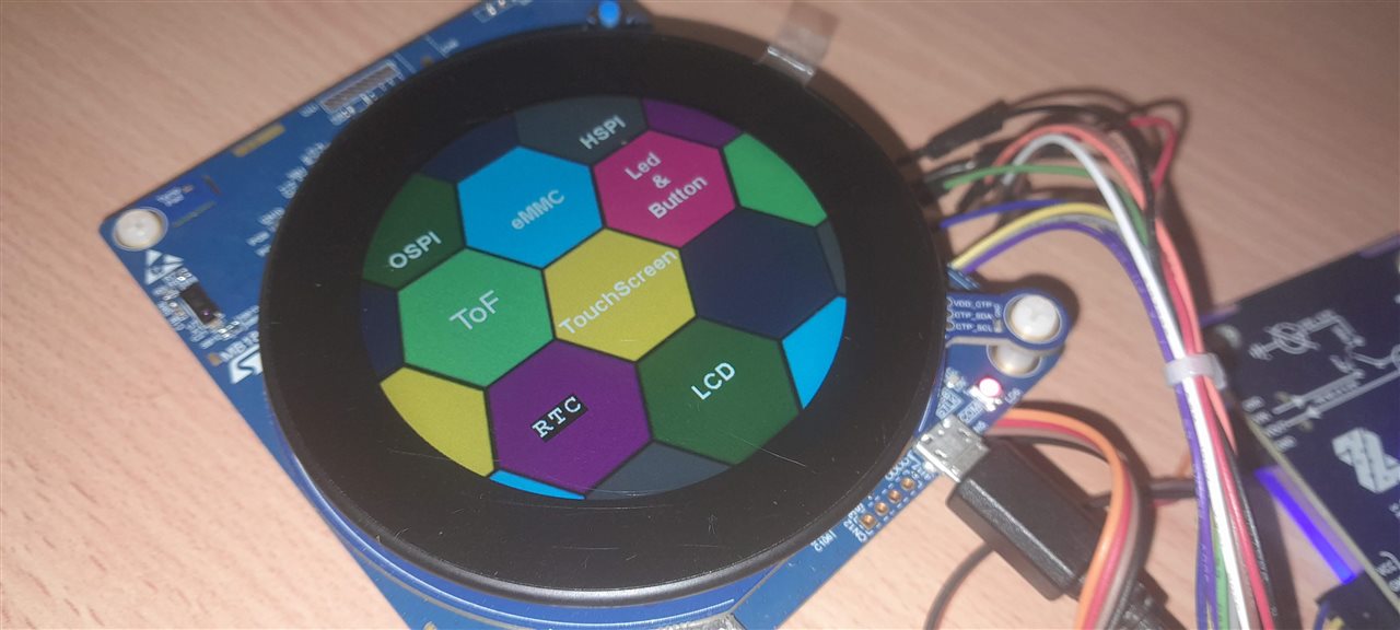
IMAGE TITLE: THEN IMAGE DESCRIPTION |
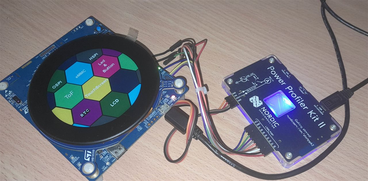
IMAGE TITLE: THEN IMAGE DESCRIPTION |
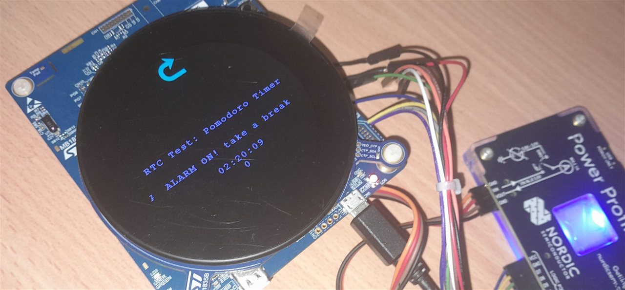
IMAGE TITLE: THEN IMAGE DESCRIPTION |
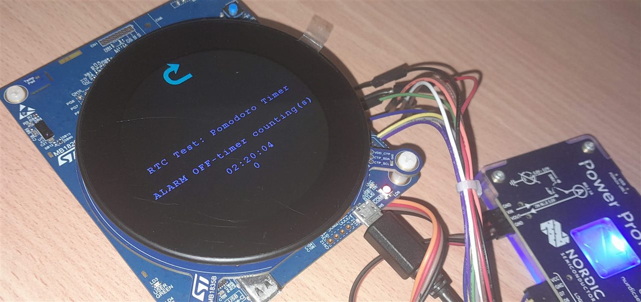
IMAGE TITLE: THEN IMAGE DESCRIPTION |
You don't have permission to edit metadata of this video.
The STM32U5 project in CubeIDE provides a window for LPBAM configurator within the .ioc file during the project creation which can be modified likewise any other .ioc file throughout the development process. The LPBAM window has 3 tabs - 'LPBAM Scenario and Configuration', 'Pinout and Configuration' and 'Clock Configuration' which can be separate in its own domain than the one over .ioc Pinout and Configuration. The code generation for this LPBAM Configurator happens once the flow is saved and moved out to the .ioc file. Below is a design where the LPBAM scenario is configured around Timers and GPIO pin.

The peripherals on the left are the ones available in LPBAM mode or as a low power peripheral. As referred from the manual, these peripherals don't link to the CPU directly rather over DMA feature adding on to the power optimization. In this experimentation, the timer is initially started and one PWM_1 is configured. This drives a GPIO pin through Write_Pin_2 and the above block is again repeated again using PWM_2. The routine runs just as in the flowchart in sequence one after the other based on the parameters defined for PWM. Essentially, we'll see the two LEDs glow one after the other.

Power consumption measurements
This is another example where the power measurements are taken. The program is run as mentioned in this example https://rristm.github.io/tomas_materials_v2/RRISTM/stm32u5_workshop/master/handson0.md and the power consumption is logged.
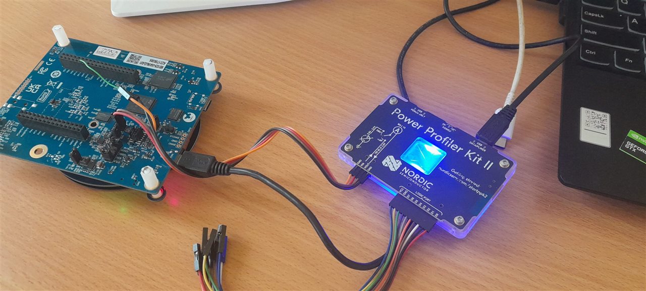

Queue 1

Queue 2

The power consumption is measured in different scenarios by varying the MSI clock speed and also the ADC sampling rates by tweaking the timer period and pulse values.
| {gallery}Power Consumption Under Scenarios |
|---|

MSI 1 |

MSI 1 and Timer values divided by 10 |

MSI 4 |

MSI 4 and Timer values divided by 10 |
Overall, this STM32U5A9-DK exhibited great performance and opens up possibilities for a vast variety of applications - namely home automation and mini electric vehicle dashboard display. Documentation was very well available and helped at each step throughout the exploration process. I found the kit well designed considering all possible usage scenarios - interrupts with ToF sensor, a large eMMC chip, current monitoring bridges separately for the MCU, 3.3V rail etc. Although I could not explore TouchGFX integration uptil now, this is what I will be continuing on further with this kit interoperating with CubeIDE's C++ TouchGFX folder package. I find the STM32U5A9 controller very suitable for smart clock application and have been asked by a couple of embedded designers about tradeoffs between STM32L0 and STM32U5. So this is one application I'll potentially be field evaluating.
| https://www.st.com/content/st_com/en/campaigns/stm32u5-ultra-low-power-mcus.html |
| https://www.st.com/en/evaluation-tools/stm32u5a9j-dk.html#documentation |
| Firmware Package and BSP https://github.com/STMicroelectronics/STM32CubeU5 |
| https://support.touchgfx.com/docs/tutorials |
| LPBAM Tutorial https://rristm.github.io/tomas_materials_v2/RRISTM/stm32u5_workshop/master/handson0.md |
| STM32U5 Training https://www.youtube.com/playlist?list=PLnMKNibPkDnFAy60ZY03q0IK8WztqQKs0 |