RoadTest: Review the ADI Software Configurable I/O Device Evaluation Board
Author: JWx
Creation date:
Evaluation Type: Development Boards & Tools
Did you receive all parts the manufacturer stated would be included in the package?: True
What other parts do you consider comparable to this product?: ANALOG DEVICES EVAL-SPOE-KIT-AZ
What were the biggest problems encountered?: sometimes sparse documentation, early version of software
Detailed Review:
AD-SWIOT1L-SL, an "software configurable Analog and Digital I/O with 10BASE-T1L Evaluation and Development Platform" is a DIN rail mountable module, factory equipped with four configurable I/O channels and Single Pair Ethernet network interface.
Powered by ARM Cortex-M4 based MAX32650 MCU with 3MB of internal Flash, 1MB of internal SRAM with addition of 8MB of external Flash and 128MB of external RAM, running open-source firmware based on Analog Device's no-OS framework, it is capable of dynamically interface any of it's four external I/O channels with the corresponding channel of either AD74413R or MAX14906, thus providing any of the following functions:
It is communicating with external system using 10BASE-T1L long range Single Pair Ethernet interface, with the option of being powered using SPoE (Single-pair Power over Ethernet).
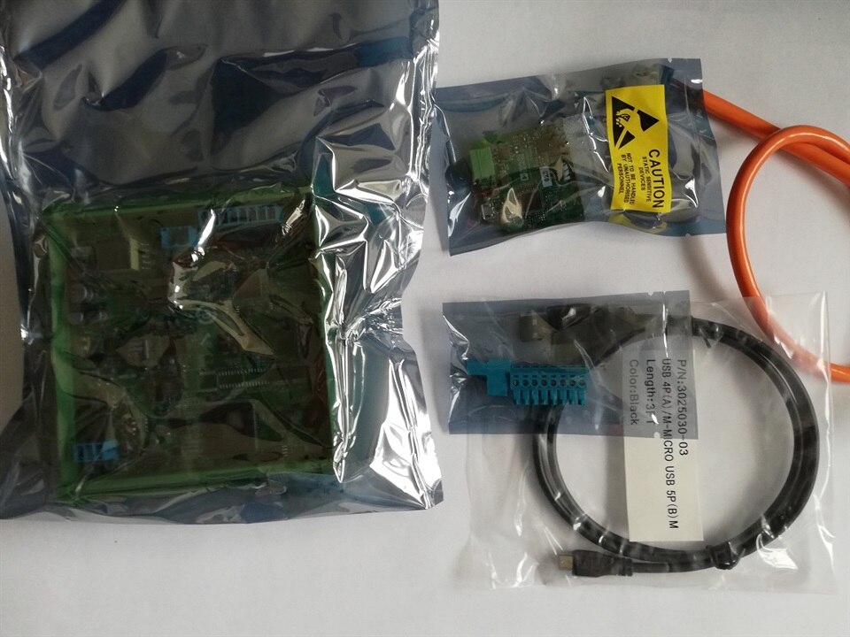
To make SPE interfacing easier, Evaluation Kit includes also AD-T1LUSB2.0-EBZ USB network adapter with 10BASE-T1L interface and the cable with matching connectors.
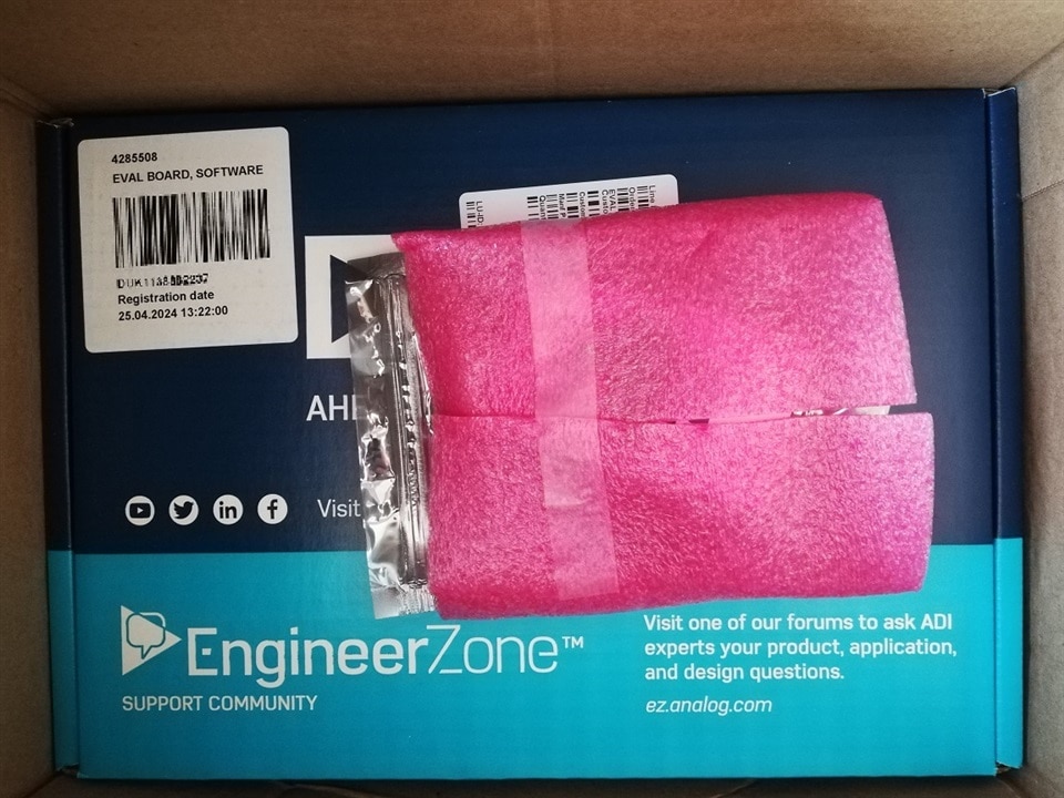
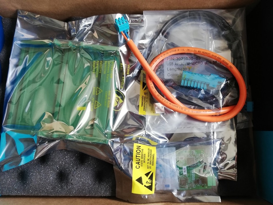
Evaluation kit was provided in cardboard box with all the kit contents inside, but no software or printed documentation (which is a kind of standard these days).
As firmware upgrade can be executed using external programmer (based on MAX32625PICO evaluation board), which is not included in the Evaluation Kit, for this Roadtest it was provided as an additional component.
Below there is a few photos of the hardware and then more detailed information about every component
| {gallery}Unboxing |
|---|
|
|
|
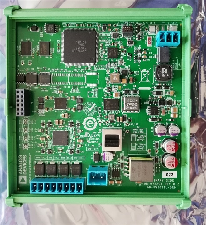
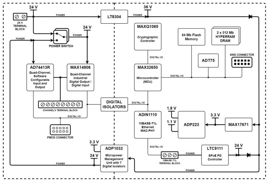
As can be seen, the module consists of two isolated parts - one connected to the "field" and one connected to the Ethernet interface, with possible power transmission both ways, which gives the opportunity to power it either using SPoE or a dedicated 24 V/2 A power supply. This second option provides more current to the MAX14906 digital interface, allowing for driving more power-consuming loads, as it is capable of supplying any of it's outputs with 1.2 A of current (and 2.4 A for a short time when Inrush Current Mode is activated).
Any of four channels available on the terminal block can be connected either to the MAX14906 or AD74413r interface, giving many possible I/O functions, configurable (and reconfigurable) at runtime. These functions include:
with many built-in diagnostics and protection mechanisms.
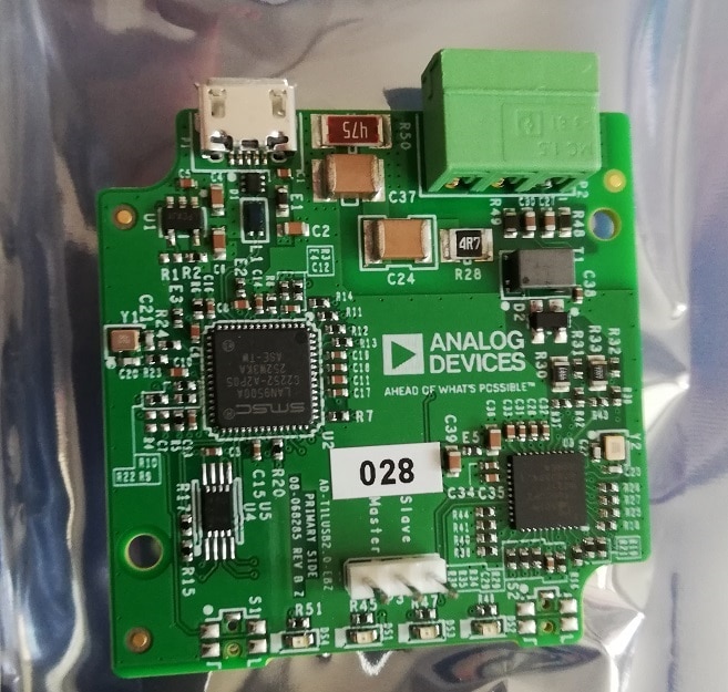
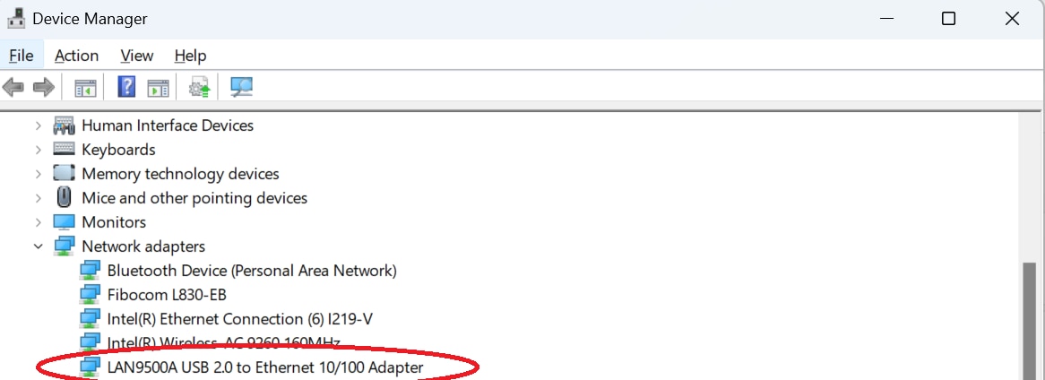
SPE adapter provided is in a form of an USB module, with terminal block interface for connecting SPE cable. Module is recognized as an network adapter "out of the box" both in the MS Windows and in GNU/Linux, and (under MS Windows) autoconfigured with the IP address that is allowing communication with SWIOT module without further changes required.

As can be seen, power, I/O channels and SPE interface are connected using pluggable terminal blocks, which allows for easy disconnection if needed while maintaining the possibility to quickly exchange the connected equipment and connector reuse. Contact are rated for currents in the range of 7-8 A, allowing for evaluation of full current capacity of the solution.
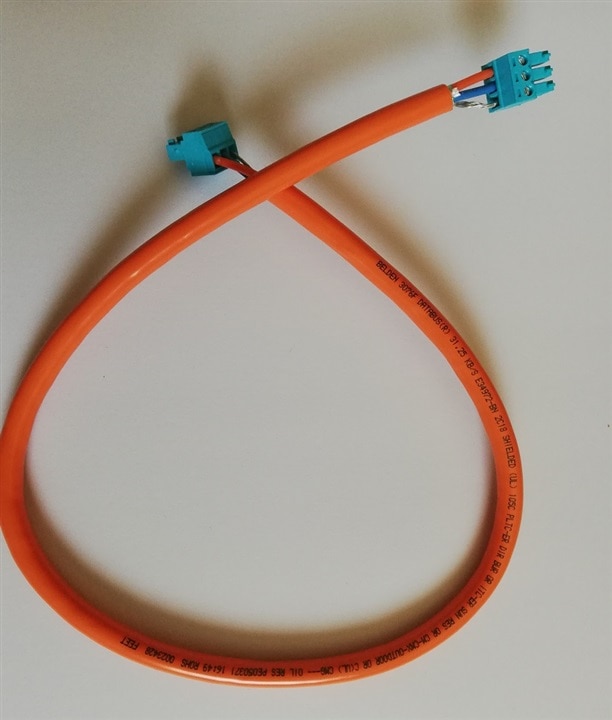
This one is really interesting - as Single Pair Ethernet patchcord, short run of Belden 3076F Fieldbus cable was provided. Shielded single pair of 18 AWG stranded copper wire, resistant to harsh environments, oil, crush, cut-out force and rodents. suitable for gas and oil extraction and refining sites and petrochemical factories. Impressive!
Another interesting fact is that it is equipped with terminal block connectors - no usual LC or dedicated industrial SPE connectors - a real improvement for development, but (in my opinion) slightly too stiff and too short. So, I have decided to conduct part of testing using different one:
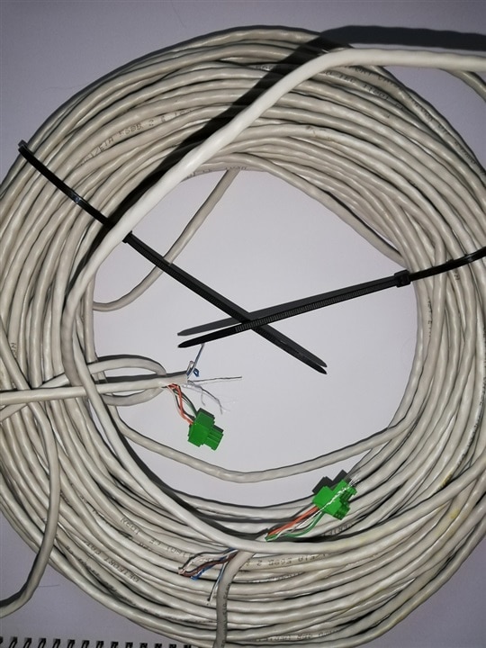
about 50 m of CAT5E UTP Ethernet cable, AWG 24, made of copper coated aluminium, where two pairs were used: one for signal and another one for ground connection (in place of the shield contact of the original cable). No communication problems arising from the new cable were observed.
At this stage I need to say that the hardware is new so the documentation is evolving.
So, using the official Getting the system up and running manual I started to wonder how to correctly power the board - simple sentence "Connect the 24V power supply" along with the overview photo does not tell much about correct polarity (one can only assume from cable colors).
This information can be obtained from the Hardware User Guide (if one looks closely on the photos) or from the PCB itself - but it is not easily identified between other text fields.
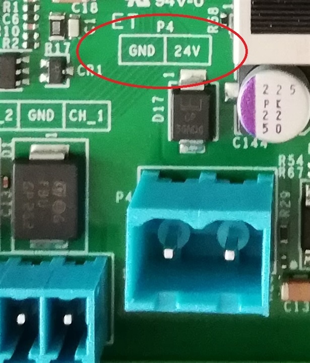
So - the documentation, at least "getting started" guide could be slightly more elaborate.
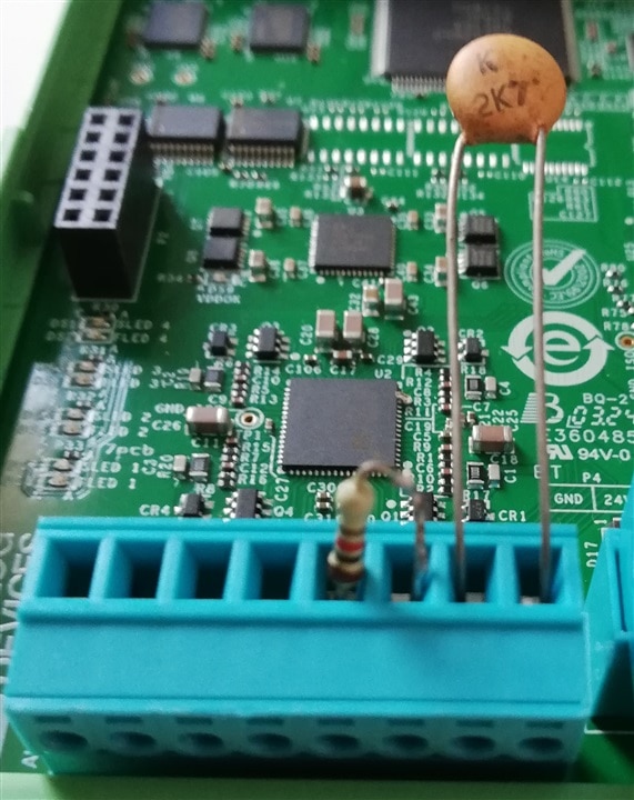
As the board can (among other values) measure resistance, for GUI tests I have connected two components: NTC termistor to the Channel 0 and fixed 1kΩ resistor to the Channel 1
For initial evaluation the manufacturer provides a version of their Scopy software, along with dedicated plugin. It needs to be installed from the following link - it seems that a new and not yet officially released version (named as "alpha") is needed
https://wiki.analog.com/university/tools/m2k/scopy/plugins/swiot1l
It has versions for MS Windows, Linux and OSX, in the case of MS Windows two flavors are provided: installable and portable one (which - in theory - can be installed on the removable disk and moved between computers).
I have started with MS Windows version. As can be anticipated, trying to use it under Windows 7 resulted in a generic error (no problem - the software is no longer supported).
Additionally, trying to use it under Windows 11 using account with non-ASCII characters in the login also resulted with a crash during startup (no error code, simply silent crash) - it has turned out that the portable version needs to write it's config somewhere in the user's profile directory and seems to not tolerate non-ASCII path. So I have created a new user account with only proper characters in the name.
Then there were some stability problems (traced later to the old firmware version on the board that was frequently returning errors, confusing the GUI. These problems were then corrected by the firmware upgrade) so I have decided to check Linux version (using Ubuntu GNU/Linux on the virtual machine).
Linux software arrives as an flatpak archive, so the install process includes installation of flatpak framework if it not exists
install flatpak

apt-get install flatpak

flatpak remote-add --if-not-exists flathub https://flathub.org/repo/flathub.flatpakrepo

flatpak install ./Scopy-208225b.flatpak

flatpak run --env=QT_XCB_GL_INTEGRATION=xcb_egl org.adi.Scopy
The last line parameter modification was needed as I am running GUI application using X11 forwarding and some graphical interface parameters were not properly propagated to the flatpak archive.
The manufacturer provides (for now) two versions of the firmware - one with fixed address and the one with address provided by DHCP. The board is pre-pogrammed with fixed IP firmware, with address from APIPA address range (169.254.97.40), which means that - under MS Windows, when SPE adapter is connected and not configured (thus being autoconfigured with APIPA address), communication can be established "out of the box".
Symbolic name swiot.local (mentioned in the documentation) is provided by multicast dns (which may need to be enabled on the workstation - if not, ip address of the board would need to be used instead). Below is a packet dump of name resolve process using mDNS:
12:45:56.822041 IP 169.254.0.2.5353 > 224.0.0.251.5353: 0 A (QM)? swiot.local. (29)
12:45:56.824107 IP 169.254.97.40.5353 > 224.0.0.251.5353: 0*- [0q] 1/0/0 (Cache flush) A 169.254.97.40 (39)
GUI operation is described in Scopy AD-SWIOT1L-SL plugin documentation and involves three phases:
At this stage, initial communication with the board is initiated, using the provided address:
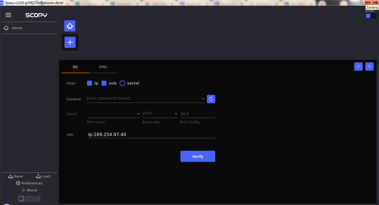
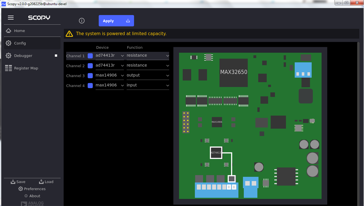
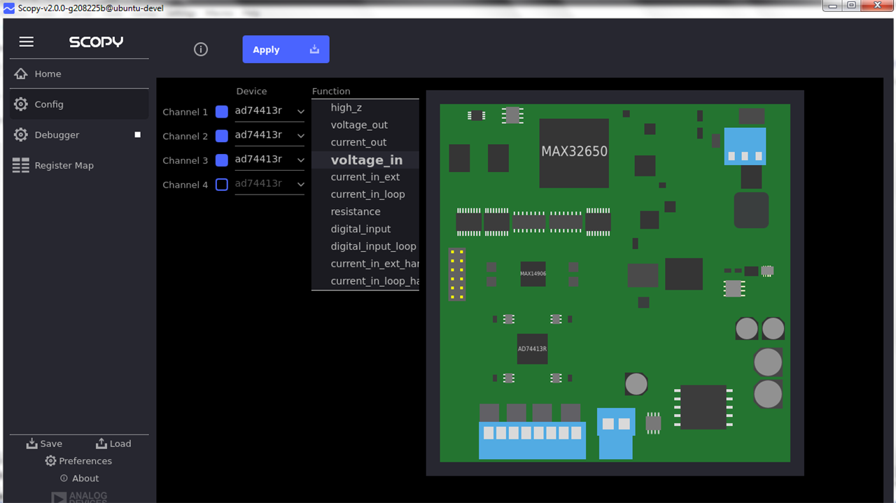
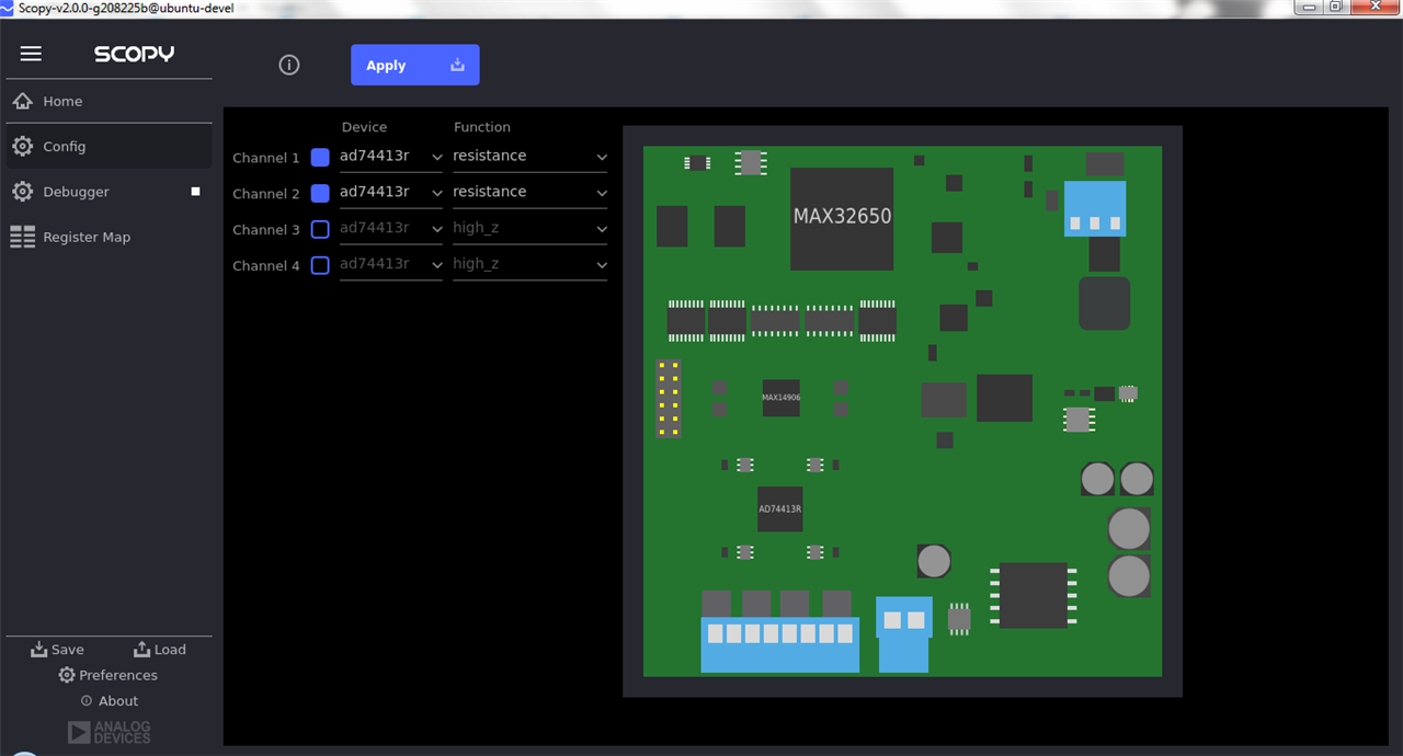
After detection, a screen with the module image appears, allowing for configuration of each I/O channel - both connection to the proper interface (AD74413r or MAX14906) and the configuration on the device
For example, using AD74413r, there is an option to select a channel first, then a device function
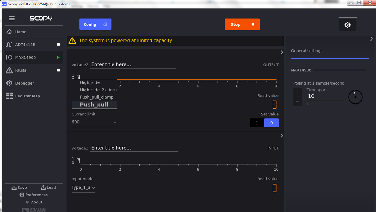
In similar way MAX14906 channels can be also configured:
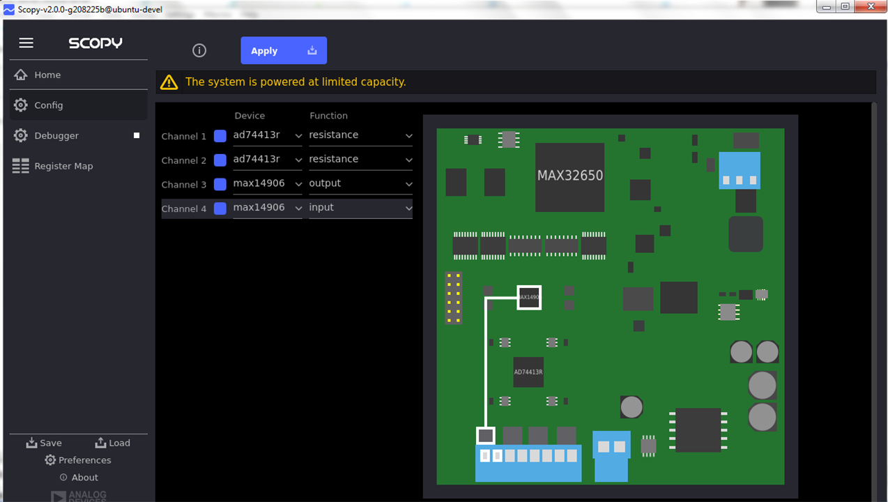
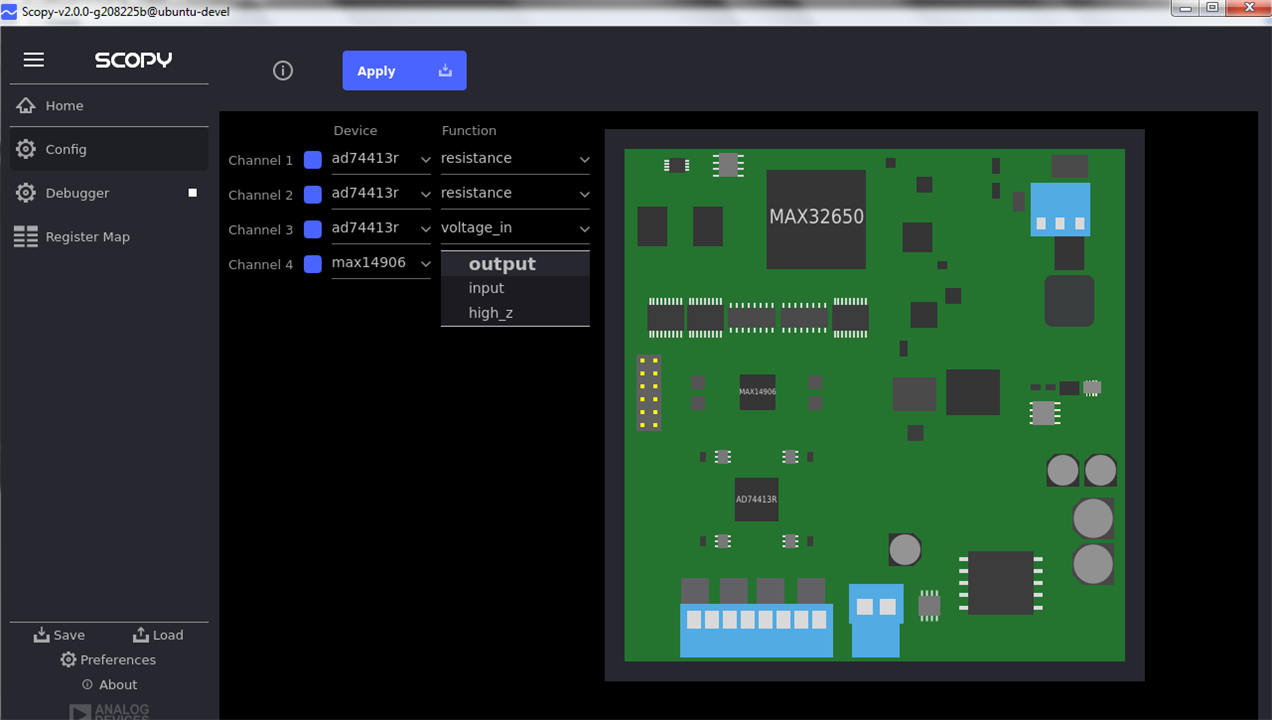
After configuration, Apply button should be clicked to switch the board into operating mode. As a side note - on the screens above, yellow warning about limited power is displayed - it should disappear when MAX14906 is connected directly to the power supply using a dedicated switch on the board, like on the screen below:
After configuration was applied to the board, different screens are available, allowing for more fine-tune interface configuration and operation. In case of MAX14906 interface, output topology can be changed here, along with current limit and output state (low or high)
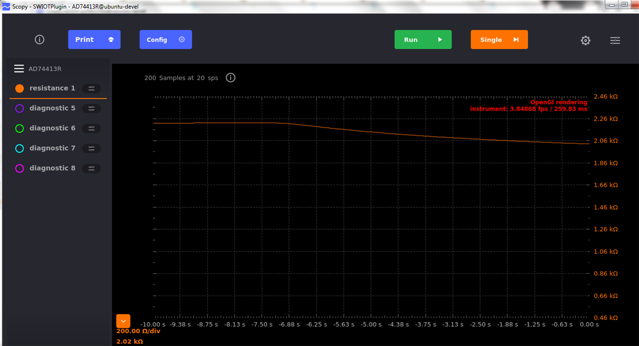
In case of AD74413r, input data is displayed in the graphical form - below is a presentation of data captured during heating of NTC termistor
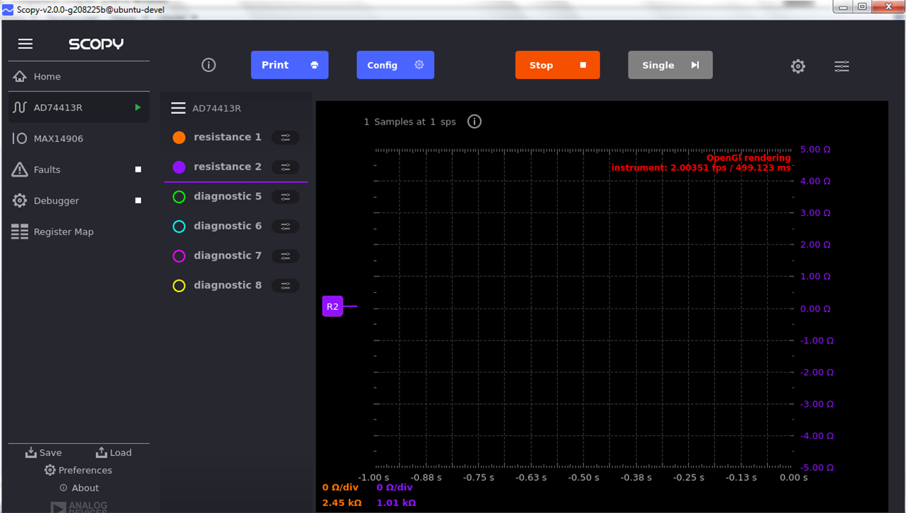
as a comparison - below there is a screenshot of the graph as above but using preprogrammed firmware - one can see that resistance values are displayed in the lower left corner of the graph but no data lines are present (probably because GUI got confused by the data returned by the board - more information in the next paragraphs)
Last element I wanted to test was a possibility of controlling SWIOT from user's code. Analog Devices is providing a SWIOT dedicated branch of their Python PyADI-IIO library at https://github.com/analogdevicesinc/pyadi-iio/tree/swiot, so - after installing it along with the prerequisites (mainly pylibiio and numpy from the public pip3 repository) I have started exploring example scripts.
Unfortunately - after modification allowing for reading resistance value from the channel 0 or 1 (to read value of my NTC or fixed resistor), they were exiting with the exceptions after several readings. It seems that the board from time to time returns -22 value that is triggering exception withing iio library. This situation can be observed in network packet dump from the execution that ended with the exception:
[configuration phase ommited]

READ iio:device3 INPUT resistance1 processed
7
1013019
READ iio:device3 INPUT resistance1 processed
7
1013019
READ iio:device3 INPUT resistance1 processed
-22

EXIT
Catching this exception allowed for getting the series of measurements using the code as follows (based on swiot.py example):
import adi
import numpy as np
AD74413R_DAC_MAX_CODE = 8192
dev_uri = "ip:169.254.97.40"
[...]
channel_config = ["resistance", "resistance", "resistance", "resistance"]
channel_enable = [1, 1, 0, 0]
channel_device = ["ad74413r", "ad74413r", "ad74413r", "ad74413r"]
swiot = adi.swiot(uri=dev_uri)
swiot.mode = "config"
swiot = adi.swiot(uri=dev_uri)
swiot.ch0_device = channel_device[0]
swiot.ch0_function = channel_config[0]
swiot.ch0_enable = channel_enable[0]
[...]
swiot.mode = "runtime"
ad74413r = adi.ad74413r(uri=dev_uri)
max14906 = adi.max14906(uri=dev_uri)
adt75 = adi.lm75(uri=dev_uri)
swiot = adi.swiot(uri=dev_uri)
[...]
for i in range(100):
    try:
        resistance = ad74413r.channel["resistance0"].processed
        print(resistance)
    except:
        print("Exception has occured!")
This discovery have effected in another test iteration - this time after the firmware upgrade.
Last available firmware (of the fixed IP address flavor and revision d76f2a1 - dated at 29.V.2024) was downloaded from https://github.com/analogdevicesinc/no-OS/releases, then flashed using MAX32625PICO board based programmer.
As in many recent frameworks, firmware upgrade was as easy as copying firmware file into virtual disk presented by the programmer when connected using USB (detailed procedure is included in Software Users Guide).
After the upgrade, many problems observed previously have disappeared - PyADI-IIO script stopped generating exceptions, correct graph of measured resistance in SCOPY software have appeared, stability problems of GUI largely disappeared.
SWIOT module is an interesting evaluation kit, giving the opportunity to evaluate many new components and technologies (SPE connectivity for example), but - as it is fairly new and under development , one should be prepared to encounter some errors and the necessity to upgrade both the firmware and possibly the GUI (still in alpha as of today). So - the addition of MAX32625PICO is a must as of today, but - as the module is targeted also at developers wanting to prepare their own firmware versions, they would need it anyway. In summary: a good module but undergoing growing pains as of today.