RoadTest: Review the ADI MAX32650FTHR Evaluation Kit and Accessories
Author: Abhijit Sahoo
Creation date:
Evaluation Type: Evaluation Boards
Did you receive all parts the manufacturer stated would be included in the package?: True
What other parts do you consider comparable to this product?: Nordic Semiconductor nRF52840, Espressif ESP32-WROOM-32, STM32 L4 series
What were the biggest problems encountered?: 1. Scarcity of online resources for direct drag-and-drop code for beginners. 2. During testing, an issue was encountered while using the SD Card slot on the MAX32650FTHR board. The problem may stem from a damaged SD Card slot, a one-off hardware failure that unfortunately hindered further evaluation of the MAX32650FTHR board’s logging capabilities.
Detailed Review:
MAX32650FTHR evaluation kit is the development board for the MAX32650 microcontroller. It is an ARM Cortex M4 32 bit processor with floating point support (takes care of floating point calculation). This development kit is very helpful for developing IoT, fitness bands and automotive low energy applications. With a wide variety of features available and option for battery powered, it can work quite efficiently in portable applications.
| {gallery}Product Unboxing |
|---|
|
|
|
|
|
|
|
|
Note:
The board is compatible with Adafruit Feather Board
Supports Eclipse IDE, VS code (extension), Keil, IAR IDEs
Download the Software Development Kit (SDK) from the following link:
Analog Devices SDK. For SDK installation, one can use the following link SDK installation guide. Once installed, one can use either Eclipse IDE or Visual Studio Code (VS Code) extension for firmware development. Provided below is information about installation and use of both Eclipse IDE and VS code extension.
Setup the Eclipse IDE using the following link: Eclipse IDE environment Setup
While configuring, in the select project Configuration page select the following:
Chip Type: MAX32650
Select board type: FTHR_APPS_A
Select example type: Hello_World (based on user choice)
Select adapter type: MAX32625_PICO
For development using VS Code install the following extensions:
Setup the VS Code using the following link: VS Code Environment Setup
While setting up VS Code Environment for firmware development.
In the .vscode -> settings.json use the following values for MAX32650 board
"target":"MAX32650",
"board":"FTHR_APPS_A"
Updating the MAX32625PICO (PICO) Debug Adapter Firmware:
MAX32625 PICO board firmware update
For observing output using UART over MAX32625PICO board, configure the following settings in any serial terminal:
Baud Rate: 115200, Parity: None, Stop bits: 1, Data bits: 8.
Analog Devices MAX32650FTHR Evaluation Kit "Hello World" code
The EVAL-ADXL355-PMDZ has following features:
It can be used in following applications:
To use pre-built hex file for using the accelerometer board, refer to the following link: EVAL-ADXL355-PMDZ User Guide
(In the above link, hex file link is broken, I have uploaded the hex file here: eval-adxl355-pmdz.zip )
If the code was uploaded correctly, one might obtain result like the following:
| {gallery}ADXL-355 output |
|---|
|
|
The output shows measures 3 axis acceleration
It also shows temperature measurement in millidegrees Celsius
The EVAL-ADT7420-PMDZ has following features:
Applications
To use pre-built hex file for using the accelerometer board, refer to the following link: EVAL-ADT7420-PMDZ Digital Temperature PMOD User Guide
(In the above link, hex file link is broken, I have uploaded the hex file here: adt7420-pmdz.zip)
Below is the main.C code example for doing temperature measurement, which is useful when one wants to use temperature measurement data along with other developments.
|
|
Above code is available at:
Analog Devices MAX32650FTHR Evaluation Kit "Temperature data" code
Alternatively, one can directly download this project and run it for getting temperature sensor data:
Analog Devices MAX32650FTHR Evaluation Kit "Temperature data" project
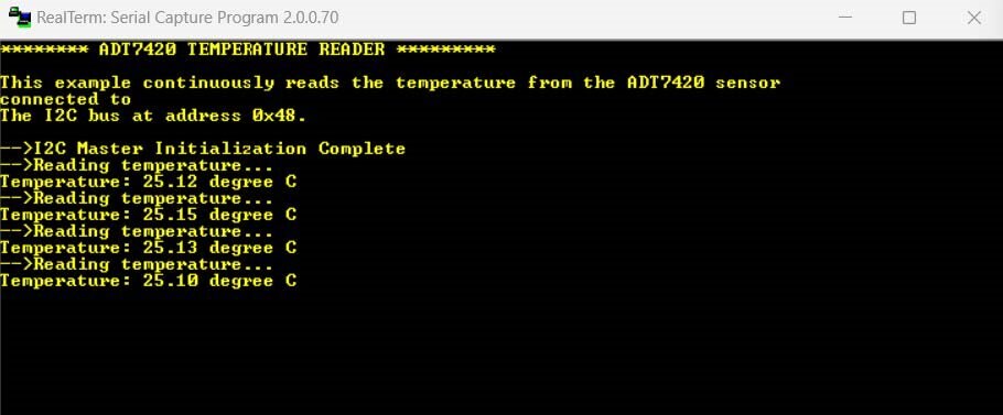
If the code was uploaded correctly, one might obtain result like the following:
| {gallery}ADT7420 output |
|---|
 |
It shows the temperature of the current environment
Example code for low power mode is available at:
Analog Devices MAX32650FTHR Evaluation Kit "Low Power" code
In the above code, to switch between different modes, one can use button (here, SW2/S2) or RTC(alarm). One should give 1 as input for enabling different power modes and 0 for disabling in the above example.
Note:
During testing, I made a mistake that resulted in damage to the MAX77818 IC in MAX32650FTHR board, due to which I was not able to do measurement of power consumption.
One can find several other example codes at following link:
Alternatively, one can find the above example codes at following location in your system locally at:
C:\MaximSDK\Examples\MAX32650
MAX32650FTHR board is a great board to work on. With a wide variety of features available, and good documentation support, the development was pretty good. I would recommend this product to anyone developing IoT, Battery powered applications and at any place where requirement of low power is necessitated for their product. With support for debugging using VS Code extension, the development becomes easier and quite smooth.
With additional components like EVAL-ADXL355-PMDZ and EVAL-ADT7420-PMDZ boards provided with the kit, it helped showcase the ease of connectivity and compatibility with other PMDZ boards. With a wide variety of applications possible, this device can be used extensively in various places.
|
Product Link |
|
|
Hardware Files |
|
|
Eclipse IDE |
|
|
SDK |
|
|
FTHR-PMD-INTZ |
|
|
ADXL355 |
|
|
ADT7420 |
|
|
MAX32650 MCU |
|
|
User guide |
|
|
Maxim SDK |