RoadTest: 3 Series MDO Mixed Domain Oscilloscope
Author: gpolder
Creation date:
Evaluation Type: Test Equipment
Did you receive all parts the manufacturer stated would be included in the package?: True
What other parts do you consider comparable to this product?: Other MDO oscilloscopes, meaning they include oscilloscope, arbitrary function generator, digital inputs and spectrum analyser. Apart from Tektronix other brands does not often combine these four options in one device.
What were the biggest problems encountered?: Just small inconsistencies in the GUI, issues with build quality, lacking sweep function for AWG. I could not find the documented aux triggering input.
Detailed Review:
Review version 1.0 - 28 Januari 2020, initial release
First, I want to thank Element14 and Tektronix for giving me the opportunity to review the 3 Series MDO Mixed Domain Oscilloscope. I am really happy that my applications was selected. This is a real great instrument.
It's a honour to be selected to review the first place of The Favorite Products Roadtested in 2019.
For such equipment, with much interest, 112 applicants in this case, it is not easy to write a convincing application. To be transparent, and also to inspire other members, for future roadtests, my application follows here:
(a) Where did you first learn about this RoadTest (e.g., Facebook, Twitter, Linkedin, Instagram, element14 website, element14 member, newsletter, etc.)
element14 website.
(b) Describe your technical background, including your test equipment expertise.
I'm a researcher computer vision and robotics with a bachelor degree in electronics and a PhD in applied physics.
I work for a agricultural university/research institute as a senior researcher/project leader for application of vision techniques for quality assessment of plants.
Besides being a researcher I also teaches computer vision at bachelor level, and for experienced researchers during our summerschool on imaging.
As a licensed ham radio operator I'm also quite experienced in RF electronics.
I have a strong background in electronic and optical test equipment, starting with multimeters and component testers, up to oscilloscopes and RF spectrum analysers.
On element14 I reviewed four oscilloscopes and a spectrum analyser (full list in the answer on question e).
(c) Why did you apply for this particular roadtest?
This is a very interesting device, especially since it combines an analog / digital oscilloscope and a random function generator with rich functionality with a real RF spectrum analyzer.
This integrated approach minimises rack or bench space, which is great.
Moreover, the quality of the display, which has a high resolution, is not compromised.
I am very curious if there are also disadvantages when so much functionality is put into one device. This is one of the aspects that I will take into account when performing the review.
(d) What is your testing procedure or project plan (Be as specific as you can)?
The plan is divided in three tasks:
- analog/digital oscilloscope
- RF spectrum analyser
- arbitrary function generator
Analog/digital oscilloscope
For the evaluation of the oscilloscope I let me be guided by the excellent articles on reviewing oscilloscopes by Colin O'Flynn of circuit cellar, as I also did in my previous reviews. Here is the full list of topics:
- Topic 1-1: Do You Want a PC-Based or Stand-Alone Instrument?
- Topic 1-2: Where’s the Ground?
- Topic 1-3: Input Types
- Topic 1-4: Probe Quality and Type
- Topic 2-1: Analog Bandwidth
- Topic 2-2: Sample rate
- Topic 2-3: Equivalent Time Sampling
- Topic 2-4: ADC Resolution
- Topic 3-1: Memory depth
- Topic 3-2: FFT Length
- Topic 3-3: Segmented buffer
- Topic 3-4: Remote Control/Streaming
- Topic 3-5: Decoding Serial Protocols
- Topic 3-6: Software Features
- Topic 4-1: Triggering Methods
- Topic 4-2: External Trigger Input
- Topic 4-3: Arbitrary Waveform Generator
- Topic 4-4: Clock Synchronization
I will specifically compare the results to the oscilloscopes I tested previously. In particular the PICOSCOPE 5444D MSO - USB Oscilloscope which has reasonable high specifications.
RF spectrum analyser
For the RF spectrum analyser I will compare the performance to the R&S® FPC1000 - 3GHz Spectrum Analyser
for the following applications:
- Measuring harmonics of HAM radio transmitters.
- Exploring home automation signals on 433 MHz.
- Measuring filter characteristics.
- Calibration a DDS-60 VFO for WSPR transmissions.
I will have a critical look at:
- center frequencies and span
- scan speed
- resolution bandwidth
- video bandwidth
- noise levels
- detector
Arbitrary function generator
Up till now I never saw an arbitrary function generator with a frequency range up till 50MHz, which means that signals can be generated in the HF frequency range.This gives the opportunity to use it for instance for testing bandfilters in combination with the spectrum analyser. I'm also curious whether it has a digital output, which was lacking on the PICOSCOPE 5444D.
Planning
In general, 60 days are sufficient for a sound review. But since this is a very versatile device, I wonder if an assessment period of 60 days is sufficient in this case.Therefore I already proposed to extend the review to 90 days, with mandatory updates after e.g. 30 and 60 days? Since I'm not in the position to make this decision, I herewith provide a planning for both options. First the week planning for 90 days period (12 weeks):
Task Week 1 Week 2 Week 3 Week 4 Week 5 Week 6 Week 7 Week 8 Week 9 Week 10 Week 11 Week 12 prepare, gather documentation, unboxing oscilloscope tests topic 1 oscilloscope tests topic 2 oscilloscope tests topic 3 oscilloscope tests topic 4 First roadtest (blog) update RF Spectrum AnalyserMeasuring harmonics of HAM radio transmitters. RF Spectrum AnalyserExploring home automation signals on 433 MHz. RF Spectrum AnalyserMeasuring filter characteristics. RF Spectrum AnalyserCalibration a DDS-60 VFO for WSPR transmissions. Second roadtest (blog) update Test arbitrary function generator (analog up till 50 MHz) Test arbitrary function generator (digital) Wrap up spare/unforeseen Final roadtest (blog) writing
In the event that we have to adhere to the 60-day period, I unfortunately have to cut back on activities. The oscilloscope part is the same, but for the spectrum analyzer I have removed the applications for home automation and DDS calibration. The digital part of the function generator is also removed. Moreover, the planning runs a greater risk because there is no longer free time to solve unforeseen problems.
Task Week 1 Week 2 Week 3 Week 4 Week 5 Week 6 Week 7 Week 8 prepare, gather documentation, unboxing oscilloscope tests topic 1 oscilloscope tests topic 2 oscilloscope tests topic 3 oscilloscope tests topic 4 First roadtest (blog) update RF Spectrum AnalyserMeasuring harmonics of HAM radio transmitters. RF Spectrum AnalyserExploring home automation signals on 433 MHz. RF Spectrum AnalyserMeasuring filter characteristics. RF Spectrum AnalyserCalibration a DDS-60 VFO for WSPR transmissions. Second roadtest (blog) update Test arbitrary function generator (analog up till 50 MHz) Test arbitrary function generator (digital) Wrap up spare/unforeseen Final roadtest (blog) writing
(e) Have you participated in the element14 community? If so, provides some links to what you've done. If you are a new member, answer "New Member."
I'm a active member of Element14. Recently I got the third price in the Upcycle It Design Challenge as wel as in the Pi IoT Smarter Spaces Challenge.Up till now I completed 17 RoadTest reviews, a complete list can be found here. In this specific roadtest I would like to compare the performance of the 3 Series MDO Mixed Domain Oscilloscope with scopes and a spectrum analyser reviewed before:
- PICOSCOPE 5444D MSO - USB Oscilloscope - Review
- 3GHz Spectrum Analyzer - R&S® FPC1000 - Review
- BitScope Micro Oscilloscope & Analyzer - Review
- Tektronix TBS1202B-EDU Oscilloscope - Review
- Picoscope 2205A Oscilloscope - Review
(f) What does "being a professional" mean to you?
Provide the proposed deliverables in time and according to the standards.
(g) Can you complete testing and review writing on element14 within 60 days from the receipt of the product? (Yes, No, Maybe, Explain)
Yes.
See the proposed planning in the work plan with options for 60 days and an extended period of 90 days.
(h) I understand that if I do not complete the roadtest review on element14, you will be required to return the product back to element14 at your own expense? Answer yes or no
Yes
For the convenience of the reader, here some links to information I used when performing this roadtest review.
Mixed signal oscilloscopes (MSO) have the ability to display signals in both the time and frequency domains. In the time domain, they can display synchronised analog waveforms, digital waveforms, and decoded serial protocols. With the help of a fast fourier transform (FFT) they can display signals in the frequency domain. An arbitrary/function generator is built-in for signal generation. A mixed domain oscilloscope (MDO) contains an integrated spectrum analyzer signal path for a much better frequency domain analysis. MSO scopes are available from all major brands, while not many companies make MDO scopes. Tektronix is one of them and the MDO 3 series of this road test is a representative of MDO scopes.
Below is an informative video from Tektronix, explaining the differences between the various scope types:
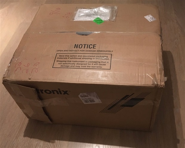
A rather large box was delivered by UPS, so I was a bit afraid to find something in there like:

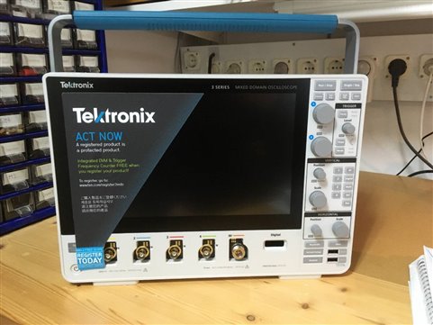
But luckily that was not the case:

A large piece of packing material and a beauty of an oscilloscope.

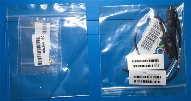
In the corner of the box was a goody bag with a lot of items:
| {gallery} Accessories |
|---|
|
All assessories |
|
four TPP0500B passive probes |
 |
 |
|
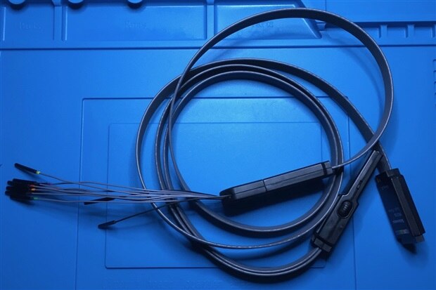
16 channels digital probe cable assembly |
|
Two lead-sets general purpose 8 channel digital probe |
|
|
 |
|
Two probe tip sets (10 pieces each) |
|
Probe tips (pins, 2x10) and probe alligator ground, probe identification two each for 5 colours. |
|
N to BNC adapter for connecting BNC connectors the RF input |
|
Power cord (not suitable for me, as the connecter is US standard) |
|
Accessory bag |
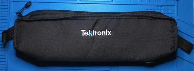 |
Also quite a bit of paper documentation, including:
Installation and safety manual and calibration data report and certification.


There are some interesting differences when you compare my unboxing with the official unboxing by David Korfman from Tektronix:
After unboxing I could not wait and immediately switched on the device. What stands out is that the fan starts blowing loudly for a short time and a nice picture shows up on the screen. Than it takes quite long for the scope to boot, 69 seconds in total, compared to 40 seconds for the Tektronix TBS1202B, 10 seconds for the Siglent SDS 1072CML and a few seconds for my old analog TRIO scope for warming up the cathode ray tube (Tektronix TBS1202B-EDU Oscilloscope - Review ).
A big label covering the screen asks me to act and register the scope. For which I in return got the Integrated DVM software option.
Talking about software options, next to the software options offered in the roadtest review, a 400 days demo license for all other options was also installed.
About box before:

and after registration:
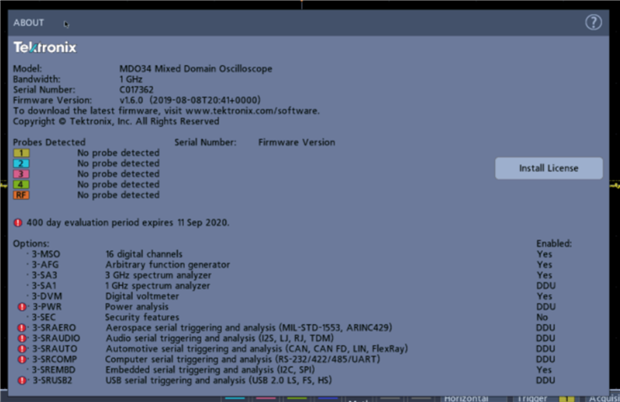
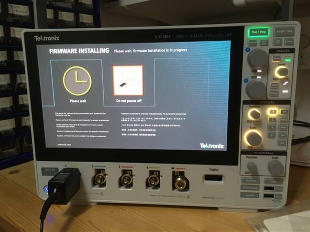
The supplied documentation suggests me as a first step to check the firmware and update if needed. The installed version was indeed outdated, so I immediately upgraded to firmware version 1.6.0. This process went smoothly:
| {gallery} Firmware upgrade |
|---|
|
|
|
|
|
|
|
|
Although in general the build is quite robust and has some nicely thought features, I noticed some cosmetic damage as I looked further around the unit.
This was also the case for my fellow roadtester, Donald Lane, who found almost the same issues (Tektronix 3 Series MDO - Part 1: First Impressions).
On the right side of the handle some scratches next to one of the screws, and the other Torx screw replaced by a Phillips type.

On the back a loose screw and also some slack between the front panel and the rest of the housing:
To my opinion, this is not what is expected from a device worth 15k$. It is not acceptable if this is a new device coming from the production line.
I expect the device has some history and is used/tested earlier, also teared down a bit, although I expect only the back was removed, since the calibration void sticker was still in place.
For the oscilloscope evaluation, I was guided topic by topic by the excellent articles on reviewing oscilloscopes by Colin O'Flynn of circuit cellar, as I also did in my previous reviews.
Personal preference determines your choice for a standalone or PC based instrument. Colin gives a nice consideration for choosing between them.
I have some experience with different scopes, from an old analog low bandwidth to nice digital bench top scopes from Siglent and Tektronix. And USB bases scopes from BitScope and PicoScope. Modern stand-alone scopes often have the option for remote operation through USB or Ethernet. I have to say that I didn't used this option much, I mainly used scopes in standalone mode. A major advantage of PC-Based scopes is the large screen of your laptop where you can display several signals at once in high resolution.
Another advantage is that screenshots and data already are on your PC, so no need to transfer them for further processing using USB sticks.
A big disadvantage of the PC-Based scopes is that there are no knobs. When peeking and poking in my electronic designs to find the fault, or try to tune the circuit to its best performance, I like to press buttons or tune knobs, in stead of choosing menu items and fill in input boxes. But as already said this is a strict personal preference.
Given these considerations, the MDO34 gives the best of both worlds, except that it is less portable than smaller scopes.
The MDO34 has:
Related to this there are several options for remote operation, which I will explain under topic 3-4.
Tektronix has a nice video, that briefly demonstrates the user interface in about 2 minutes:
The ground for the input channels of this scope is connected to system 'Earth', as is with almost all standalone scopes. The Ground and Probe Compensation connectors are located at the lower right side of the instrument, near the front panel. The Ground connector (a small hole in the case, see picture below) provides an electrically grounded (through a resistor) connection point to attach an anti-static wrist strap to reduce electrostatic damage (ESD) while measuring.
Also the Probe Compensation connections provide a ground connector (upper tab) the lower tab provides a 1 kHz square wave source for adjusting the high-frequency response of a passive probes, I will come to that later.

For measuring differential signals with isolated inputs Tektronix provides a number of dedicated probes, either low and high voltage, as well as optical isolated probes. Be aware that these probes are very expensive. Information can be found at the scopes webpage, by selecting probes from the menu: https://www.tek.com/oscilloscope/3-series-mdo-mixed-domain-oscilloscope.
Regarding the scope inputs, looking at the specs, the capabilities of the MDO34 are quite advanced. Four inputs with a max rating of ± 300V (RMS) CAT II with peaks ≤ ±425 V for an impedance of 1MΩ (same as TBS 1202). Much more than the PicoScope oscilloscopes. The input impedance can also be set at 50Ω. In that case the max input range is 5V (RMS) with peaks ≤ ±20 V. Input can be either AC or DC for 1MΩ and only DC for 50Ω.

This 50Ω input option is a very valuable feature for RF measurements.
The input range is 1 mV/div to 10 V/div for 1MΩ and 1mV/div to 1V/div for 50Ω.
The 1GHz bandwidth is 5 times more than the PicoScope 5444D and Tektronix TBS 1202B and 40 times more than for the PicoScope 2205A.
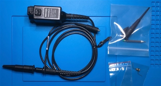
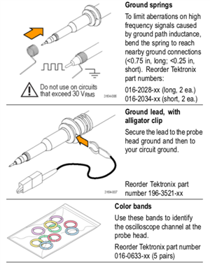
The scope comes with four standard passive probes (part number TPP0500B). The probes are rated at 500 MHz with fixed 10:1 attenuation. Maximum voltage rating is 300V (CAT II), 3.9/10Mohm. Included are:
 |
 |

The quality is comparable to the Tektronix TPP0201 probes I reviewed earlier(Tektronix TBS1202B-EDU Oscilloscope - Review ) and in my opinion much better than the PicoScope probes (PICOSCOPE 5444D MSO - USB Oscilloscope - Review ). The BNC connector is different from the TPP0201, as these probes are uniquely identified using a pin connection on the probe. This way the scope knows which probe is connected, and stores the compensation values for each probe/channel combination and automatically recalls the compensation values when you plug in the probe again. Probe compensation status is shown in the Probe Setup panel of the Channel configuration menu.
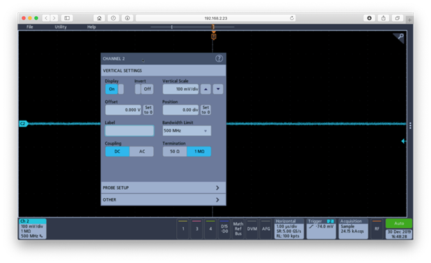
The probe compensation is done via an automatic procedure from the scope rather than by adjusting it with a screwdriver, as can be seen in the screenshot below:

BTW, I'm curious how this probe identification is implemented, is it just a stored serial number? Which protocol is used? As there is just one pin, I expect something like the 1-wire protocol. If you know more about this, or did a tear-down of a scope and/or probe, please let me know.
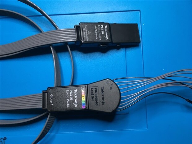
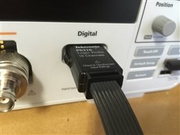
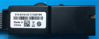
The digital probes is much better than the PicoScope probe pictured below:

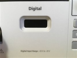
The probe socket is positioned deep inside the housing. The probe connector can firmly be connected, using a locking mechanism. The connector breaks out 16 data channels over two 80 cm cables, ending in 2x8 pin headers. The pin headers can be connected to interchangeable flying leeds with a ground connection on each end and eight signal lines in between.


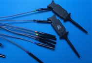
Also a set of micro hook tips and pins are supplied for each of the headers, making it a very versatile probe set.

The MDO34 is a very versatile scope, has many functions and as such is equipped with digital inputs that I personally am very happy with. Whether you see this as an advantage or not is somewhat a personal choice: you may want to have a separate stand-alone digital analyzer, or you want it built into your oscilloscope. Colin O'Flynn opts for a stand-alone digital logic analyzer, because digital logic analyzers are available at a relatively low price from different manufacturers. In his experience, the cost of purchasing a separate PC-based logic analyzer is considerably lower than the "incremental costs" of selecting an oscilloscope with logic analyzer capabilities compared to one without. That may be a good consideration given the high cost of digital input options for the MDO34:
|
Option |
Description |
Price |
| 3-MSO | Tektronix 3-MSO *Internal Option* Adds 16 Digital Channels, Including P6316 Digital Probe and Accessories, to 3 Series MDO Unit | €1,620.00 |
| 3-SRAERO | Tektronix 3-SRAERO *Internal Option* Adds Aerospace Serial Triggering and Analysis (MIL-STD-1553 and ARINC 429) to 3 Series MDO Unit | €1,250.00 |
| 3-SRAUDIO | Tektronix 3-SRAUDIO *Internal Option* Adds Audio Serial Triggering and Analysis (I2S, LJ, RJ, and TDM) to 3 Series MDO Unit | €1,250.00 |
| 3-SRAUTO | Tektronix 3-SRAUTO *Internal Option* Adds Automotive Serial Triggering and Analysis (CAN, CAN FD, LIN, and FlexRay) to 3 Series MDO Unit | €1,250.00 |
| 3-SRCOMP | Tektronix 3-SRCOMP *Internal Option* Adds Computer Serial Triggering and Analysis (RS-232/422/485/UART) to 3 Series MDO Unit | €1,250.00 |
| 3-SREMBD | Tektronix 3-SREMBD *Internal Option* Adds Embedded Serial Triggering and Analysis (I2C and SPI) to 3 Series MDO Unit | €1,250.00 |
| 3-SRUSB2 | Tektronix 3-SRUSB2 *Internal Option* Adds USB Serial Triggering and Analysis (USB 2.0 LS, FS, and HS) to 3 Series MDO Unit | €1,250.00 |
| 3-BND | Option 3-BND - Application Bundle; Bundle for 3 Series MDO (Includes 3-SRAERO, 3 SRAUDIO, 3-SRAUTO, 3-SRCOMP, 3-SREMBD, 3-PWR, 3-SRUSB2) | €3,380.00 |
(*) prices are in euros and based on https://www.tek.com/tekstore/configure/MDO34.
The 3-MSO option enables the digital input hardware and includes the digital probes, the other (software) options are for decoding serial protocols for specific applications. It is not expected that all of them are needed by a single user, but to me 3-SRCOMP and 3-SREMB are quite basic. All in all it is costly to add digital input and some protocol analysis to the scope. Compare to the PicoScope 5444D with a price difference of $250 between plain and MSO version it is way more expensive.
Furthermore the PicoScope can standard decode: 1-Wire, ARINC 429, CAN, CAN FD, DCC, DMX512, Ethernet 10BASE-T, Fast Ethernet 100BASE-TX FlexRay, I2C, I2S, LIN, Modbus ASCII, Modbus RTU, PS/2, SENT Fast, SENT Slow, SPI, UART (RS-232 and RS-422, RS-485) USB, without additional costs.
When selecting an oscilloscope, the “rule of thumb” is to select one with five times the analog bandwidth of the highest–frequency digital signal you would be measuring. This Roadtest MDO34 is equipped with the 1 GHz bandwidth option, meaning you can measure signals up to 200 MHz. Of course you can measure higher frequencies as well, but the waveform will be affected as higher frequency components are attenuated. A 1 GHz bandwidth means that at 1 GHz a sinusoidal signal is measured at -3 dB which is equal to half the power, or 0.7 times the voltage.
Would be great to check the -3dB points using a signal generator, as I did in my Tektronix TBS1202B-EDU Oscilloscope - Review, but unfortunately I don't have a calibrated signal generator going up in frequency that high, therefore I just had a look to a 145 and 430 MHz signal from a hand held radio.
I made a pickup loop by connecting the ground clip of the probe to the tip, and put that over the antenna:

Resulting in the following signals:
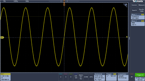
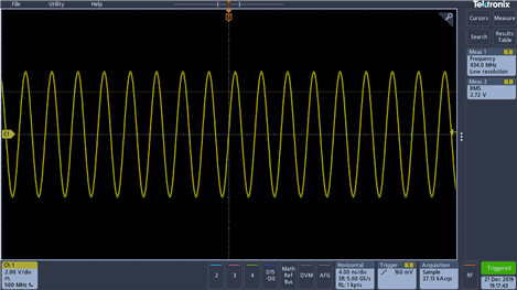
Proving that the scope (and probe) are capable of measuring signals up to ~ 500 MHz.
Specifically the 430 MHz signal is much better than displayed on the PicoScope 5444D:

Although the scope is rated at 1GHz bandwidth, this is only the case for a 50 ohm input. When using the high impedance input the bandwidth is 500 MHz. This also explains the 500 MHz bandwidth of the attached probes.


For 50 ohm the coupling is fixed at DC, where for 1 Mohm also AC can be selected.
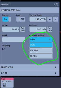
There also is the option to limit the bandwidth if a lower bandwidth is sufficient. Lower bandwidth limits noise and can provide a cleaner view of the signal.
To demonstrate the different bandwidths for 50 and 1M ohm input termination, I connected a 3 GHz noise source to channel 3 using 50 ohm termination ( 1 GHz bandwidth) while at the same time, using a pick-up coil, the same signal on channel 1 using 1 Mohm termination (500 MHz bandwidth) was measured. On both channels a measure badge was placed, showing the statistics of the measured frequency.

As can be seen the mean (u) and max (M) frequencies of the signal are larger for channel 3, proving the larger bandwidth of this 50 ohm terminated channel.
The maximum sample rate of the MDO34 is 5 GS/s when using 2 channels, or 2.5 GS/s when using 3 or 4 channels. 5 GHz comes down to one sample per 200 ps (picoseconds). To demonstrate this I connected a RF noise source, with a bandwidth of 3 GHz. Compared to the PicoScope 5444D the nice thing of this scope is the 50 ohm input. So the output of the noise generator could be directly connected to a scope input. For safety I put a 10dB attenuator in between.

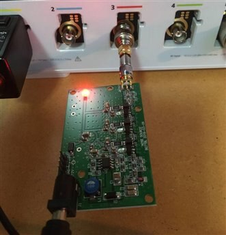
The shortest horizontal scale is 400 ps/div, which at a sample rate of 5 GHz amounts to two samples per division.
Here you see how this signal looks like. The trace is drawn using (smoothed) vectors.

It is possible to display the signal only with points, from which you clearly see the two points per division:

Although the bandwidth of the noise signal is much larger, it is not shown due to aliasing.
When the time span (horizontal scale) is enlarged, you see more and more detail.
| {gallery} Noise signal with increased time span |
|---|
|
1 ns |
|
10 ns |
|
100 ns |
|
1 us |
The sample rate is determined by the horizontal scale (time/division) and the record length (the total number of points sampled). For the last screenshot above, the sample rate is 5 Gs/s for a horizontal scale of 1 us/div and a record length of 10Mpts.

When the record length is decreased to its minimal value (1 kpts) the sample rate is decreased to 100 Ms/s.

The PicoScopes support what they call 'Equivalent Time Sampling' ETS. This mode makes it possible to acquire more samples than the standard sample rate determines. This high sample rate is achieved by doing careful phase shifts of the A/D sampling clock to sample “in between” the regular intervals. This requires your input waveform be periodic and very stable, since the waveform will actually be “built up” over a longer time interval. Read the articles of Colin O'Flynn for a detailed description of this mode. The MDO34 doesn't support this mode. To me that is not a big issue for a scope with a standard sample rate of 5 GS/s. In stead the MDO34 supports some other sample/acquisition modes like: Sample (the standard), peak detect, high resolution, envelope, average, FastAcq™ and roll mode.

The modes are well described in the manual.

FastAcq™ is trademarked by Tektronix and reduces the dead time between waveform acquisitions, enabling the capture and display of transient events such as glitches and runt pulses. Fast acquisition mode can also display waveform phenomena at an intensity that reflects their rate of occurrence.
A nice demonstration of this functionality is demonstrated in the following video by Tektronix:
The typical ADC resolution seems to be 8 bits for most scopes, but there are high end models with a higher-resolution too. The MDO34 sticks to 8 bit, which in my opinion is a bit disappointing given it's a high-end/high price oscilloscope. If you want a higher resolution mixed signal Tektronix scope, you should go for a 4,5 or 6 series, who have a resolution of 12 bit. The PicoScope 5444D is better in that sense, since it has a FlexRes resolution that can switch between 8/12/14/15/16 bits (PICOSCOPE 5444D MSO - USB Oscilloscope - Review ).
I did some measurements of a 500mV triangle wave from the arbitrary function generator, using various vertical scales, to show the effect.
Below are the screenshots, at 100mV/div and 2V/div.


In order to have a better look at the 2V/div signal, I saved the waveforms in a csv file and plotted them using a spreadsheet program. This clearly shows the quantisation noise in the 2V/div signal caused by the ADC resolution.

There is a trick though to increase the vertical resolution, by using the Hi-Res sampling mode. In that mode the resolution is advertised as 11 bit by Tektronix.
Hi-Res mode is a Tektronix-patented process that calculates and displays the average of all the values in each sample interval. It runs at the highest sampling rate of the digitiser, providing maximum detail in the acquired waveform.
Below the pictures of the same signal as above:


The signal quality has clearly improved, but one must realize that this improvement is not caused by a higher ADC resolution, but by a sampling trick. It seems that there also is an artefact in the slope of the signal.
The digital oscilloscope works by sampling an ADC and then stores these samples in memory. Therefore an important consideration will be how many samples it can actually store. This especially becomes apparent at the high sample rates (5 GS/s) of the MDO34. The MDO34 is able to record 10Mpoints on all channels. Which means that at the maximum sample rate 2 ms of data can be stored. This is much less compared to the PicoScope 5444D with a memory depth of 512 Mpoints. In general, Tektronix does not seem to equip their scopes with large amounts of memory. The TBS 1202-EDU (Tektronix TBS1202B-EDU Oscilloscope - Review ) standard can store 2.5k samples, while a cheap Chinese Siglent scope I owned in the past, had a memory depth which is just 5 times smaller than the MDO34.
From the horizontal menu you can play with different record lengths. As input I used a 500 kHz square wave and used the zoom function so that the full recorded signal is displayed in the upper part of the screen. Samples are displayed as points rather than vectors, in order to demonstrate the sample interval.
| {gallery} 50 kHz square wave at different record lengths |
|---|
|
|
|
|
 |
 |
 |
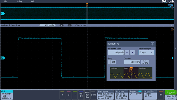 |
What stands out is that when switching from 1 kpoints to 10 kpoints, the sample rate automatically increased tenfold from 50 - 500 Gs/s, the same when switching from 10 kpoints to 100 kpoints, where the max sample rate of 5 Gs/s is reached. During these steps the total time captured is the same, but more points are captured. When the record length is increased further, the total captured time is increased as can be seen in the upper graph. When doing the same steps in reversed order this is not the case, and the total recorded time span remains the same.
I'm not sure whether this is a bug or a feature?
Topic 3-2: FFT Length
Although the MDO34 is equipped with a real spectrum analyser, it also has the FFT function in the scope mode. The FFT process mathematically converts the standard time-domain signal (repetitive or single-shot acquisition) into its frequency components. The FFT function processes the waveform record and displays the FFT frequency domain record, which contains the input signal frequency components from DC (0 Hz) to 1⁄2 the sample rate (also called the Nyquist frequency). The buffer size for the FFT is important as it determines how many points are used in calculating the FFT. This will also define the number of “bins” (i.e., horizontal frequency resolution) in the output graph. With a limited FFT length you are not able to zoom in on a small part of the spectrum, as thoroughly described by Colin O'Flynn (https://circuitcellar.com/cc-blog/evaluating-oscilloscopes-part-3/). The MDO34 luckily uses the whole memory length selected in the acquisition, which allows you to zoom in and still obtain accurate results. Counterside of this is that a FFT using a large buffer size takes quite some time.
Below two examples, the same square wave as used above (500 kHz) with FFT over 100 kpoints and 1Mpoints, you clearly see the uneven harmonics of the square wave showing up in much larger resolution for the 1Mpoints sampled signal. The first FFT takes about 1 s, while the second takes almost 14 s.


A feature considered by Colin almost as a “must-have” is a segmented buffer. This means you can configure the oscilloscope to trigger on a certain event, and it will record a number of waveforms of a certain length. This option can speed up the ability to find glitches that occur only occasionally. In contrast to the PicoScope scopes, the MDO34 doesn't have this option, but there are other options available for finding glitches, such as the FastAcq method described previously, or advanced trigger functions described later on in this review.
For emote control operation The MDO34 is equipped with a LAN port and an USB port. Available software is Tektronix own solution, 'KickStart Instrument Control' only for Windows PC's and TekVISA and IVI drivers for use with general purpose software like LabView and MATLAB. I'm not completely sure whether this also works on macOS and it's not part of my roadtest plan to test this.
However, the LAN connection provides some very interesting functions. The first one I would like to mention is the possibility to mount an external file server for storing screenshots and data. I have a small file server in my home network, just a USB stick on my home router, which I connect to the scope. This file server is also connected to my laptop. In this way the scope data can be transferred to my laptop very easily. This is a major improvement compared to exchanging data by swapping the usb stick in and out of the scope and laptop.

Another nice option is remote connection to the internal web browser in the scope. When pointing your browser to the scopes IP address you will see the scopes home page:

Then by selecting Instrument Control, you will get the scopes screen in the browser, from which you can control the scope.
Unfortunately only the mouse can be used as input device. The keyboard doesn't work. I hope this functionality will be implemented in the near future.
Also the screen resolution is less than on the scope itself, including the saved screenshots:

On the other hand, the scope itself does not have an option to record a video of the signal. With this remote option this can be done easily using the screen record function of your laptop:
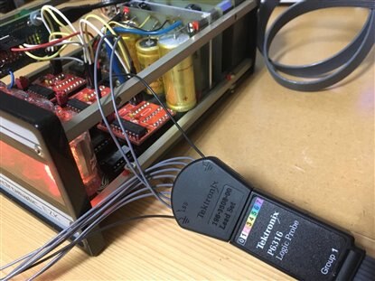
Like in my PICOSCOPE 5444D MSO - USB Oscilloscope - Review, I tested serial protocol decoding on one of my latest project, where I2C is used to program a couple of PCF8574AN, 8 bit I2C I/O extenders, connected to BCD drivers for displaying numbers on nixie tubes ([Upcycle It] Nixie Display - Index).
The MDO34 digital probe easily connects to the pin headers on the board:


The Bus configuration menu is used to define a bus from which to acquire, decode, and display data, by tapping the Add Math Ref Bus button on the Settings bar and then tap Bus to add a Bus badge to the Settings bar and add a bus waveform to the screen.

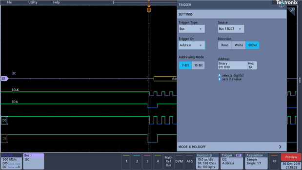
A very nice feature is the possibility to trigger on the I2C data or address byte.
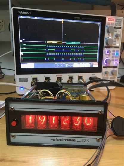
The example below shows triggering on the three different addresses (38,39 and 3A) used for the three I/O extenders in the nixie display.
| {gallery} I2C triggering on different addresses |
|---|
|
Select Address trigger |
|
Address 38 |
|
Address 39 |
|
Address 3A |
In the video below the trigger fires on '00' in the data field, which is when the clock reaches 00 seconds:
For me this address and data trigger option is a very handy feature, which is not available on the PicoScope 5444D.
It is currently common for high-end oscilloscopes to be manufactured with all necessary hardware for high-end use, but this hardware is shielded with software, so that software keys must be purchased for various options. It is much cheaper for a manufacturer to manufacture osciloscopes in this way, because they only need to set up one production line. The customer then determines what he ultimately needs and pays for it. I’ve already mentioned it a few times in passing, but you should always check to see what features are actually included in the offered price quote. With the MDO34 it is no different. The base price of the MDO34 is already quite high as mentioned on the roadtest description (MDO34-1000MDO34-1000). I was surprised to find out about the prices of the features.
Depending on whether you need a scope with two or four channels, you can configure your options at https://www.tek.com/tekstore/configure/MDO32 and https://www.tek.com/tekstore/configure/MDO34. I have made an overview based on the 4-channel version, which can be found in the table below.
For the 2-channel version, prices for the base unit are around 20% cheaper than for the 4-channel version.
|
Option |
Description |
Included in Roadtest |
Price |
Total |
|
3-BW-100 |
100 MHz Bandwidth for analog channels |
|
€4.260 |
|
|
3-BW-200 |
200 MHz Bandwidth for analog channels |
|
€4.770 |
|
|
3-BW-350 |
350 MHz Bandwidth for analog channels |
|
€8.900 |
|
|
3-BW-500 |
500 MHz Bandwidth for analog channels |
|
€12.000 |
|
|
3-BW-1000 |
1000 MHz Bandwidth for analog channels |
1 |
€14.800 |
€14.800 |
|
3-AFG |
Arbitrary function generator |
1 |
€834 |
€834 |
|
3-MSO |
16 Digital Channels, Including P6316 Digital Probe and Accessories, to 3 Series MDO Unit |
1 |
€1.620 |
€1.620 |
|
3-SA3 |
Spectrum analyzer 9kHz – 3 GHz |
1 |
€2.780 |
€2.780 |
|
3-SREMBD |
Embedded Serial Triggering and Analysis (I2C and SPI) to 3 Series MDO Unit |
1 |
€1.250 |
€1.250 |
|
TPP0500B |
Passive probe 500 MHz |
4 (part of 3-BW-1000) |
€503 |
|
|
P6316 |
16 Channel MSO probe |
1 (part of 3-MSO) |
€649 |
|
|
|
|
|
---------- |
|
|
|
|
|
Total: |
€21.284 |
(*) prices are in euros and based on https://www.tek.com/tekstore/configure/MDO34.
Note that the analog probes are included in the base price, as well as the digital probe for the 3-MSO option.
As you can see a higher bandwidth substantially increases the price. And also the options like the spectrum analyser, arbitrary function generator and digital input costs a lot. You might be able to buy a dedicated version of these instrument with similar specifications for a price which is not much higher. Having everything in one device though has its advantages.
The digital protocol analysis options, already mentioned in topic 1-5, are subdivided in seven software options, each selling for €1.250. You can buy them all bundled for €3.380, which is saving you up to €5.370 (Which to me just shows how insanely expensive all these software add-ons really are!).
The MDO34 is equipped with a number of powerful trigger options, including:
I already demonstrated bus triggering in topic 3-5. In order to demonstrate some other options I constructed a sine wave with anomalies in Matlab, and put it in the arbitrary function generator.
This code:
signal = sin([0:pi/100:(100*pi)-(pi/100)]); % 50 period sine wave
signal([5001:5100])=0; % one half period the signal is zero
signal([8001:8100])=1; % another half period the signal is 1

create_mdo34_arb(1000,signal,'test_signal_ARB'); % create csv file for arbitrary function generator (topic 4-3)
plot(signal,'-');
Generated this signal:

In the video below first an edge trigger is used, this trigger is unable to display the anomalies. Then a pulse width trigger is applied, when increasing the trigger level to almost 1V, the square wave period is detected. The same for a timeout trigger, with a time limit of 1us. Then a runt trigger, with an upper and lower threshold close to 1 triggers on the square period. When lowering the lower threshold just below 0, the 0 period is triggered. Finally a rise time trigger while decreasing the time limit to 1.7us detects the square period again.
Most oscilloscopes also have an “external trigger input.” that can be used for triggering, meaning your trigger channel doesn’t count against your “ADC channels". It seems like the MDO34 doesn't have an external trigger input, but the documentation is confusing. Both the pdf manual as the help function mention the option for external triggering using "AUX input".

But there is no port labeled that name on the front or on the back.

Also the Source setting in the trigger menu does not show the 'AUX' option.

Am I missing the external trigger input? I don't think so, because with the MSO option you can also trigger on the digital channels. Furthermore, I rarely use four input channels, so I have the option to use one as a trigger source.
So no AUX input, but what about the AUX output? From the I/O menu this port can be selected to output a pulse at:

The first and the last one are evident, but I have no idea what is ment by 'event occurrence', I also could not find any reference to that from the documentation.
Remember the video in topic 4-1? Here is another solution for triggering the signal with anomalies. I selected AFG Sync on AUX output, connected this output to channel 3 on which also the trigger was selected. Isn't it a nice signal?


I’ve already mentioned the arbitrary waveform/function generator (AFG) a few times in passing, bit didn't explain it in detail. This € 800 option has quite some nice features.

Contrary with the PicoScope 5444D, the MDO34 can output digital signals as the low level of the square wave can be set to 0V and the high value to 5V (TTL) or one of the other logic standards (3.3-V, 2.5-V, 1.8-V, and 1.5-V).

For using the arbitrary waveforms I wrote a small matlab function to write a matlab signal in a csv file format needed by the scope:
function create_mdo34_arb(frequency,signal,filename)

l=length(signal);
time=1/frequency;
timestep=time/l;

fid = fopen([filename '.csv'],'w');

amplitude = max(signal)-min(signal);
fprintf(fid,'Model,MDO34\n');
fprintf(fid,'Firmware Version,1.6.0\n');
fprintf(fid,'\n');
fprintf(fid,'Waveform Type,ARBITRARY\n');
fprintf(fid,'Frequency,%f\n',frequency);
fprintf(fid,'Amplitude,%f\n',amplitude);
fprintf(fid,'Offset,0\n');
fprintf(fid,'Label,\n');
fprintf(fid,'TIME,ARB\n');
for i=0:l-1
    fprintf(fid,'%f,%f\n',i*timestep,signal(i+1));
end
fclose(fid);
end
And this is how a typical csv file looks like, (example from topic 4-1):
Model,MDO34
Firmware Version,1.6.0

Waveform Type,ARBITRARY
Frequency,1000.000000
Amplitude,2.000000
Offset,0
Label,
TIME,ARB
0.000000,0.000000
0.000001,0.187381
...........................
.............
0.000999,-0.187381
0.001000,-0.031411
Despite the nice features, I'm a bit disappointed with the AFG. What I'm really missing is a sweep function. I was in the impression that I was stupid and just couldn't find it, but didn't notice any programming functions for the waveform generator in the help function, manual and website. It seems a bit strange not to have a sweep function, given all the different predefined waveforms that have been put into the generator, where some of them are so specialised and have less use than a sweep function for the majority of users.
Standalone function generators on the market, with a price tag equal or less to the 3-AFG option, mainly have two outputs, and are able to sweep and in most cases also to modulate a signal with AM, FM, PM and more.
Another issue is related to the number of bits used for the vertical resolution. Where all standalone function generators, also the ones from Tektronix list this value in the specifications, I again felt a bit stupid as for the 3-AFG I could not find any information on this.
Clock synchronisation is a technique to synchronize the sample rate to an external device, either by outputting the clock from the oscilloscope, or feed in an external clock into the oscilloscope. An applications is synchronizing a capture between multiple oscilloscopes. Another one is synchronised capture for a software-defined radio (SDR).
The MDO34 doesn't support output or input of the sample clock.
Due to size restrictions for blog posts, the review part of the spectrum analyser can be found in a separate post, here:
To finish up this review, in conclusion the MDO34 mixed domain oscilloscope is great, the total feature set is enormous. Actually it is, as advertised by Tektronix a Mixed Domain Oscilloscope which means that an analog and digital oscilloscope are combined with an arbitrary waveform generator and RF spectrum analyser, all in one device. I really like the large touchscreen and the intuitive user interface. For me also a great feature is the knobs on the right hand side of the front panel. Remember that I missed the knobs when reviewing the PICOSCOPE 5444D MSO - USB Oscilloscope - Review. Specifications are also great, 1GHz bandwidth for the scope, 3GHz for the spectrum analyser, max 50 MHz for the AWG, to name a few. Also the very advanced triggering methods both analog and digital are great. Furthermore I love the excellent connectivity features, such as instrument control from a connected web browser and the possibility to store data and screenshots on a remote fileserver.
Having said that, there are also points for improvement. First the build quality of the device delivered was not what to expect for such expensive equipment. Although this might be something specific for this roadtest device which might have some history. Anyway my fellow roadtester had the same experience. I already mentioned the device is expensive. This is mainly due to the high prices for the different options, as mentioned in topic 1-5 and 3-6. The 8 bit ADC is disappointing, the much cheaper PICOSCOPE 5444D goes up to 16 bit. Also compared to PicoTech, the record length is not overwhelming, but similar to other bench top scopes. The scope is lacking the documented aux triggering input. What really strikes me is that a sweep function is missing on the AWG. For the price of the AWG option you can purchase a decent stand-alone function generator with more options than included in the MDO34. This is also the case for the spectrum analyser, where I miss a video bandwidth setting and some measurement options, such as harmonic distortion.
The attenuation setting and max level on the spectrum analyser are confusing, not to say it is a bug in the software.
Thanks for reading, and if there are any questions left, please post them in a comment on this review.