RoadTest: TI-PMLK Buck Experiment Board: TPS54160 & LM3475
Author: Jan Cumps
Creation date:
Evaluation Type: Evaluation Boards
Did you receive all parts the manufacturer stated would be included in the package?: True
What other parts do you consider comparable to this product?: You can run these experiments with other Buck converters too. You'll get different figures in your experiments and you'll have to consult the datasheet of the components you use. You can consider parts of other manufacturers if you prefer.
What were the biggest problems encountered?: No problem related to the kit. My lab lacks some of the test equipment needed to get a full and clean view of the signals (oscilloscope current probes). Ask access to your uni or company electronics lab.
Detailed Review:
The Buck Experiment board is an educational kit. My review focuses on that aspect.
If you want to boost up your Buck design knowledge and see what happens in a real circuit, this kit is great.

The package is a combination of a Lab Kit and an Experiment book.
The Lab Kit is a PCB with 2 Buck converter circuits. Both circuits are independent and they show different regulator strategies.
The components are laid out in a way that gives you access to virtually all signals - on the regulator side and on the power side.
The most important part of the kit is the Experiment book though. And that's available as a free download.
It contains little theory. The expectation is that you know how Buck converters work and that you can do the math.
So not just knowledge of the principle, but also determine loss, ripple, etc.
That said, the book gives a refresher at the start of each experiment and gives all formulas needed to do this.
The 6 lab experiments cover the characteristics and behaviour that are of interest to switch mode conversion designers.
That includes looking at the signals under ideal circumstances. But you 'll also introduce instability and see what happens then.
There's a methodology to the way you're guided through the labs. I'll show a few highlights of experiment 2: Impact of passive devices and switching frequency on current and voltage ripples.
You can find the details of experiment 1 in my related blog - see the links at the end of this review.
| Run n Experiment | Post-Lab Review |
|---|---|
 |  |
You get an explanation of the purpose of the tests, case study and a theory refresher (click the images to enlarge).
 |  |  |
This sets the scene. If you are in a power circuit design course (or followed one that covers Buck converters), this won't be new for you.
If your knowledge level doesn't cover these topics, I (really - it's excellent) advice this online course: Power Electronics Specialization.
The experiments in this kit are a good match of what that curriculum covers on Buck regulators.
The theory related to the current exercise is briefly recapped in the book though, and all equations needed to perform calculations are given.
The next section explains how to wire up the experiment. First the hook-up of the instruments.
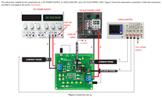 |  |
Then the configuration for each of the test in that experiment. There are several of them per lab.
| Test 1 | Test 2 |
 | 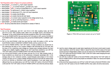 |
 |  |
These tests give insight into the workings of the Boost converter. And they relate that to the theory behind them.
And that's where the practical part of the lab ends. Each experiment closes with a review of the outcomes.
 |  | 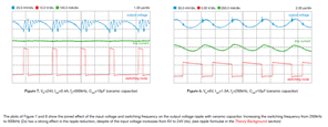 |
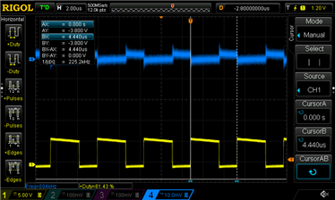
You can compare your measurements and scope captures with the ones from the book.
You may gain an additional skill here: see how sloppy probing plays a real role in the measurements of these circuits and improve on that.
 |  |
The hardware is two independent Buck converters. Both work on different regulation and control principles.
The LM3475 is a Hysteretic PFET Buck controller, the TPS54160 a step down converter.

Some of the labs drill down into those mechanisms and use them to show the different operation modes of converters, while others could be run on either of the circuits.
The booklet doesn't go deep into the working of the regulators. As mentioned in the preface:
The reader is also strongly invited to read the manufacturer’s datasheets of all the parts mounted in the boards, especially the control chips, to improve the knowledge and the understanding of each device. A good knowledge of the power supplies implemented on the boards, supported by the heuristic observations and the models and methods discussed in the book, help the user to distinguish what can be done from what cannot be done. |
You can see that spirit in the design of the board. All things of interest are sample-able.
Both circuits are in essence pure Buck converters. The LM3475 circuit has a feedback voltage divider in the output. Otherwise it's that typical switching transistor and diode pair plus output inductor and capacitors.
The other circuit is more elaborate (but you'll recognise the Buck configuration).
You'll have to look a little closer though. The switching power transistor is part of the regulator IC.
In both circuits you can configure a few things that influence switching frequency, inductance,smoothing.
As told earlier, these settings also allow you to show bad designs, one of my favourite topics of this kit.

I've documented how I work with the kit. Check the links at the end of the article.
Great kit that allows you to experience the theory in reality. It's focus is on the mechanisms that matter when designing a Buck converter circuit.
You need to know Buck theory fairly well to get the value out of the experiments. This kit will not learn you how a switch mode converter works.
You need a well equipped lab to complete all measurements (especially to probe the switch node currents).
Don't let that stop you though. You can get a lot of results out of it with a power supply, a meter, an oscilloscope and flexible load resistance.
| Related Blog |
|---|
| 1a: 1st Experiment Set-up |
| 1b: 1st Experiment Lab Setup |
| 1c: 1st Experiment Measure |
| 2: Educational Value |


