RoadTest: Silicon Labs BLE Explorer Kit + Air Quality Bd
Author: BigG
Creation date:
Evaluation Type: Development Boards & Tools
Did you receive all parts the manufacturer stated would be included in the package?: True
What other parts do you consider comparable to this product?: Nordic Semiconductor nRF52 modules, such as the nRF52833 for example.
What were the biggest problems encountered?: For an application development perspective, I found that there's a lack of complete examples for all the basics (Nordic Semiconductor nRF52's infocenter provides a best in class, in my opinion). For example, when learning how to create an I2C master application I did not find any Simplicity Studio 5 examples other than a couple in GitHub, which do not tie in with the official documentation. Also, when learning to use the BGAPI to create a Network Co-Processor (NCP) Host Application it was difficult to work out how it functions as examples were either obscure (e.g. audio example) or too simplistic (e.g. empty example). Then, the search function in docs.silabs.com does not work very well. For example, I open up a function in docs.silabs.com and type that function name in the search box - it then returns all sorts of results and certainly never places the page I need (i.e. the one I'm on) at the top of the list. This makes searching for function details very tedious and slow.
Detailed Review:

Firstly, I would like to thank Element14 and Silicon Labs for providing me with the BGM220 Explorer Kit (BGM220-EK4314A).
Besides my Silicon Labs BGX13P Bluetooth Design Kit roadtest and running demo software on a Thunderboard Sense board, I am someone who has never attempted to develop custom firmware using any of Silicon Labs Wireless development kits before. So this my opportunity to get to know this kit together with the latest IDE (i.e. Simplicity Studio 5.x) and (Gecko & Bluetooth) SDKs provided by Silicon Labs.
I'm a firm believer of the view that having great hardware without a decent firmware development environment is not much use to anyone, so for my roadtest review, I set out to ascertain the ease and speed of development using the tools and documentation provided for this explorer kit. Then once familiar with how things work, I expand and test my knowledge using the examples provided and, if time permitting, create some simple projects.
As with any new product we are often biased in our approach based on the familiarity of other related products. Then we discover during the learning process other ways of using the product which had never been considered before. In this case, I discovered that with the Silicon Labs v3.x Bluetooth Stack there is another operating mode available called the Network Co-Processor (NCP) mode. I briefly mentioned this mode in the road test, but for those who want to learn more, I created a blog about how to use NCP mode to scan for Bluetooth devices.
Let's now dive in and look at the detail.

The BGM220 Explorer Kit is an evaluation platform for the BGM220P Bluetooth Module, which has been designed to support hardware add-ons such as click boards, using the mikroBUS Socket, and breakout boards using a Qwiic Connector. There are also 2.54mm pitch (100MIL) breakout pads on either side of the board which are aligned to fit a breadboard. It is worth noting that although these pins are “aligned with breadboard dimensions”, it only fits on wider breadboard options (e.g. RS PRO Solderless Breadboard 83 x 147 x 19mm, as shown). Thus it does not fit on the more common 400-point solderless breadboards - of course you could simply use two breadboards, which works pretty well too.
The BGM220 Explorer Kit also features a USB interface, an on-board J-Link debugger, a user-LED and two buttons - one is reset & the other a user button.


On the underside of the board (bottom layer) is a Mini Simplicity Debug Connector footprint allowing you to solder on a connector itself. It’s worth noting that if a connector is soldered on you’ll have problems inserting the board into a breadboard unless extra long or double stacked header pins are used. It does seem a strange decision to place the footprint on the bottom layer, even if semi-redundant due to the onboard J-Link debugger (you'll only need the Simplicity Debug Connector if you wish to use the Energy Profiler tool). Hopefully this was not done simply to make room for logos.
The BGM220P Bluetooth Low Energy (BLE) is a pre-certified module based on the EFR32BG22 SoC (System on Chip), providing a 32-bit ARM Cortex-M33 76.8MHz processor with DSP instruction and floating-point unit for efficient signal processing.
It is the latest addition to the Silicon Labs' range of Bluetooth Modules, with both the BGM220P and BGM220S modules released near the end of 2020.

There are two BGM220 Bluetooth 5.2 module variants, namely the BGM220P and the BGM220S. The BGM220P is the larger of the two (13.0mm x 15.0mm x 2.2mm versus 6mm x 6mm x 1.3mm) and provides a slightly higher maximum TX power at +8dBm versus +6dBm from the BGM220S. It's rather curious that it is only the BGM220S that offers an RF pin for an external antenna. This is a potential shortcoming, in my opinion, for the BGM220P as there are operational cases when deploying devices out in the field that an external antenna is required for a minority of devices to improve radio signal quality. One would hardly want to create a new PCB design with a new BLE module just for these edge cases.
Despite this potential shortcoming, the BGM220P does provide a very low transmit (4.8 mA TX current at 0 dBm & 10.6 mA TX current at 8 dBm) and receive (4.3 mA RX current at 1 Mbps GFSK) output power. The BGM220P's M33 core delivers 26 µA/MHz in active mode (EM1) and 1.40 μA in EM2 DeepSleep (RTCC running from LFXO, Full RAM retention). Current consumption in EM3 mode (stopped) is 1.05 μA and in EM4 mode (classed of shutoff) is a mere 0.17 μA. Note that these values were not validated during this roadtest.
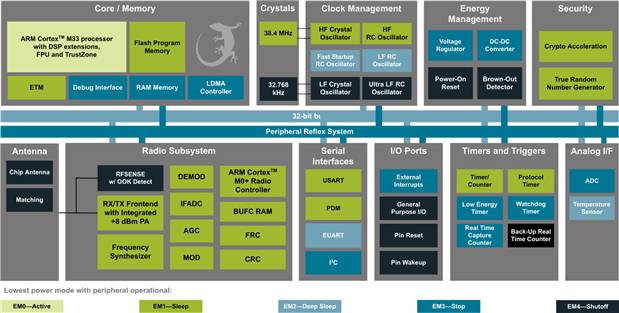
To understand which peripherals are active under which power management mode it is worth looking at the above block diagram, which can be found in the datasheets for the BGM220P modules and the EFR32BG22 SoC. So, for example, USART and PDM only operated in EM0 (Active) and EM1 (sleep) modes while ADC and I2C will continue to operate up to EM3 (Stop) mode.
What is somewhat confusing with this diagram is that not all GPIO’s will operate down to EM4 levels. This is port dependent (please refer to the EFR32BG22 data sheet for more info). So, GPIO's via Port C do not operate at the lowest power management mode while GPIO's via Ports A and B do.
It is also worth noting that within the BGM220 product family there are two variants, which have distinctive differences (highlighted in bold):
| BGM220PC22HNA2 | BGM220PC22WGA2 |
|---|---|
|
|
The are a few other Bluetooth 5.1/5.2 choices on the market at the moment, which offer Bluetooth mesh capability and the Direction Finding (AoA/AoD) feature.
For example, we have ON Semiconductor's RSL10 SiP module. This is an ARM Cortex M3 based device with an additional DSP processor. It provides 384 kB Flash, 76 kB Program Memory, 88 kB Data Memory. In my opinion, the BGM220S module would be more closely aligned to this SiP package, with its enclosed antenna. For example, the BGM220SC12WGA module has a similar size footprint (6.0 x 6.0 x 1.1 mm) and provides similar flash (352 kB of flash) but with smaller memory (32 kB of RAM).
For me personally, I thought Nordic Semiconductor's nRF52833 was the closest offering with it's mesh capability and direction finding feature. Nordic Semiconductor also have the nRF53840 module, which offers a dual core M33 processor and Bluetooth 5.1/5.2 capability.
Here is a comparison between the nRF52833 and the BGM220P (please note this is a quick extraction from datasheets and I cannot vouch for the accuracy of these details).
| nRF52833 | BGM220P |
|---|---|
Processor:
Radio Performance:
Peripherals:
Security:
GPIO’s: up to 42
Footprint (depends on vendor): NINA-B406: 10 x 15 x 2.2 mm (40 GPIO’s) EYSPDNZUA: 9.6 x 12.9 x 1.4 mm (19 GPIO’s) MDBT50-U512K: 15.5x10.5x2.05mm (42 GPIO’s) | Processor:
Radio Performance:
Peripherals:
Security:
GPIO’s: up up 25
Footprint: 12.9 x 15.0 x 2.2 mm |
Here is a visual comparison of size between the BGM220P module and a Panasonic PAN1780 (nRF52840) module as well as a Raytac MDBT50-U512K (nRF52833) module:
| PAN1780 | MDBT50-U512K |
|---|---|
 |  |

In September 2020, Silicon Labs released Simplicity Studio 5 (SS5). In a press release about the latest version of Simplicity Studio it states that SS5 now offers the same access and developer experience across a wide range of wireless protocols, all within a central web-style user interface.
However, Simplicity Studio 5 is not a simple replacement to Simplicity Studio 4 (SS4). There are still use cases where SS4 is required to develop firmware for older board types/existing projects, which use Gecko SDK 2.7 or below. SS5 only offers Gecko SDK version 3.x.x. The BGM220 Explorer Kit (BGM220-EK4314A) relies on SS5 and uses the Gecko SDK version 3.1 or higher.
I am by no means an expert with SS5 and so I found that one very handy way to familiarise yourself with the IDE was to use the links provided within the “launch page”. At the bottom of the launch page screen is a section called “Learn and Support”, which provide a number of options:

The most useful of these is the Simplicity Studio User’s Guide, which opens up your web-browser (requires Internet connection) and takes you to this page:
https://docs.silabs.com/simplicity-studio-5-users-guide/5.2.0/ss-5-users-guide-overview/
The next step in the learning and development process is to understand the different SDK's needed to develop firmware as this impacts where to look for documentation about particular SDK functions.
The first is the platform SDK, which is called the Gecko Platform (latest version: 3.2.0) and is installed by default within SS5.
The second is the Bluetooth SDK, which is referred to as Bluetooth SDK (latest version: 3.2.0.0). This SDK needs to be downloaded separately. This is typically taken care of when plugging the BGM220 Explorer Kit into the computer with USB cable and using the SS5 "Install by connecting device(s)" option.
The BGM220P, or EFR32BG22 SoC, is classed as a "Series 2" wireless Gecko platform device. The Gecko Platform is the common foundation for the Gecko SDK Suite and consists of a number of platform components:
Further detail about the Gecko SDK can be found here: https://docs.silabs.com/gecko-platform/latest/
For those who want to understand the differences or plan to migrate from a Series 1 to a Series 2 Gecko device, it is well worth reading this application note (AN0918.2): https://www.silabs.com/documents/public/application-notes/an0918.2-efm32-to-efr32xg2x-migration-guide.pdf
The Silicon Labs Bluetooth stack is a Bluetooth 5-compliant protocol stack implementing the Bluetooth low energy standard. It supports multiple connections, concurrent central, peripheral, broadcaster, and observer roles. This SDK handles GAP, GATT and Link Layer settings.
Further detail about the Bluetooth SDK can be found here: https://docs.silabs.com/bluetooth/latest/
The BGAPI is a Silicon Labs Bluetooth API which handles the interface between application and the Bluetooth stack. It allows you to create either a standalone application, where both the Bluetooth stack and the application run on a Wireless Gecko SoC or module, or an application using the Network Co-Processor (NCP) mode, where the Bluetooth stack runs on a Wireless Gecko SoC and the application runs on a separate host MCU.

I explored using NCP mode in more detail in a separate blog: Developing a desktop Bluetooth LE Scanner App using the Silicon Labs BGM220 Explorer Kit in Network Co-Processor (NCP) mode
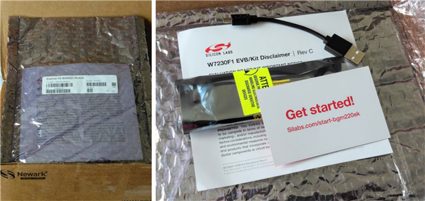
The unboxing experience is a little underwhelming, in my opinion.
I did not like the use of the clear bubble envelope, as I felt this was far too generic and lacked impact. For example, using a coloured padded/bubble envelope would’ve delivered more impact at a similar price if a branded padded/bubble envelope was too pricey (a quick search on Amazon.com and I found 50 x 4x8 inch black envelopes for $7 - at volume this would certainly be cheaper still).
Opening up the clear bubble envelope you’ll find your Explorer Kit inside an anti-static bag, a very short (4.5”) USB cable, a disclaimer leaflet and a “Get started!” business card.
Personally, I rather liked the business card. This is just the starting, or onboarding, process I'm looking for.
Using the URL (Silabs.com/start-bgm220ek) provided on the “Get Started!” card opens up the product landing page:

This landing page provides a link to the Explorer Kit’s User’s Guide (a must read document) and 5 tabbed subsections:
The Overview page is in bullet point and is broken out into different product feature categories:

It’s worth noting that on this overview page it states that the button is “with EM2 wake-up”. This is the only place this is mentioned. The User’s Guide fails to mention that there are certain restrictions with port C and the different Energy Modes (EM0-EM4). This has implications when trying out the button example provided within Simplicity Studio… more will be revealed later.
The Getting Started tab provides instructions on how to download the Simplicity Studio 5 IDE and how to install the relevant SDK for this board. This page could probably do with an additional step 3, which is to highlight examples and demos provided and point out where to find the ubiquitous “hello world” example (e.g. Platform - I/O Stream USART Bare-metal example) or the new blinky example (provided with Bluetooth version 3.2 SDK).
The Tech Docs tab provides user guides and schematics for the Explorer Kit. Then there is a link given to the information provided within docs.silabs.com. I was somewhat surprised that there is no title provided above this link as it is not immediately obvious what the link is and this link is ever so useful. The link also states “getting started” so it can easily be mistaken to refer to the previous tab, which is not the case.

The Software & Tools tab provides a link to the Simplicity Studio 5 landing page. This page could do with improvement as it fails to highlight any of the tools that are actually available for use with the board such as the NCP Commander Tool, for example (this is quite a useful tool).
The last tab is Community & Support. Here you’ll find links to the user or community forum and an option to raise a technical question with Silicon Labs. Having used both options, I found these to be excellent in terms of response time and feedback provided.
Now if you had not clicked on that link “Getting Started with BGM220 Explorer Kit” in the Tech Docs tab you may be wondering what next as there is very little guidance or wayfinding beyond what you see in those tabs. It is that minimal. For example, there is not a single link to any training material within any of the product tabs.
Thankfully, the content provided within doc.silabs.com makes up for some of these shortcomings (although it also does not provide much on Energy Modes and usage restrictions with GPIO PC07 or BTN0). What it does do well is explain how to configure the different peripheral driver options available, like UART, SPI and I2C. It even provides a useful porting guide for Arduino open source examples alongside a porting guide for Mikroe click board drivers, examples and mikroSDK.


We all have to start somewhere. This tends to start by first connecting the BGM220 board to your computer's Serial COM port with the USB cable. At least this connection process is very straightforward as Simplicity Studio 5 instantly recognises your board once connected. All you then have to do is hit the "Start" button.
This then opens up an overview page for your board. Here you are presented with a few quick start guides and you can view some documentation for both the BGM220 Explorer Kit and the EFR32BG22 SoC. However, this is not all the documentation available. There is also a separate "Documentation" tab available, which presents you with a more comprehensive set of documentation. This is quite a handy local reference (as does not require an Internet connection). However, I myself tended to rely on my web browser and search the silicon labs website as Simplicity Studio's "Filter on Keywords" option did not work very well for me as all the keywords I came up with returned zero results.
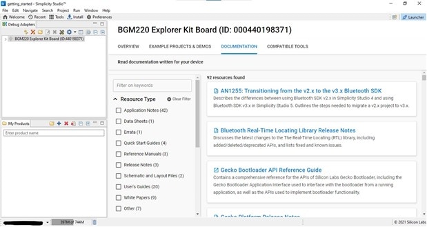
Clearly there is plenty of documentation available - e.g. 42 Application Notes and 20 User's Guides etc. That is a lot a reading to get through when starting out and I am not really the reading type. I prefer to learn by doing and so I gravitated towards the "Example Projects & Demos" tab.

The examples and demos are split into 3 "Technology Types". I focused on the two key types to get me started.
| Example | Documentation | Bare Metal | FreeRTOS | Micrium OS |
|---|---|---|---|---|
Blank c/c++ | Yes | |||
Blink an LED | Yes | Yes | Yes | |
Fade an LED (PWM) | Yes | |||
EUSART IO Stream | Yes | Yes | ||
USART IO Stream | Yes | Yes | ||
MPU Simple | Yes | |||
Use NVM3 interface | Yes | |||
PSA Crypto (multiple) | Yes | Yes | ||
SE Manager API (multiple) | Yes | Yes | ||
SPI Master | Yes | Yes | Yes | |
SPI Slave | Yes | Yes | Yes | |
Simple Button | Yes | |||
Sleeptimer service | Yes | |||
mbedTLS (multiple) | Yes | |||
| TensorFlow Hello World | Yes | Yes |
We’ll ignore the blank project.
Before diving into some of these examples, let me just say that what I really like about all these examples is the use of standardised templates for main.c and app.h/app.c. This really helped me when trying to understand the mechanics of the examples, especially when little to no detail is provided about program architecture, flow and algorithms in the example documentation.
The first 4 platform examples are very straightforward and very quick to implement. They work straight out the box. This seemed to be a logical place to start. However, beyond these four examples there appears to be no logical order (from a learning perspective) in how the examples are organised other than being in alphabetical order.

So, I jumped to the “Simple Button Bare-metal” example as this example project shows how to toggle LEDs using buttons in a bare-metal environment. Seemed easy enough to try out, or so I thought. Without proper example documentation, it caught me out and I had to spend a good deal of time, and get a bit of help from Silicon Labs excellent technical support, when trying to make sense of what was going on. The answer of course was buried in the technical detail. The user button (BTN0) on the Explorer Kit is tied to Port C, which does not work at the EM2 power management level. This is explained in the application note AN0918.2 (section 6.5) and in the EFR32xG22 reference manual - Section 25.3.6 EM2 Functionality.

So in order to get the “Simple Button Bare-metal” example to work you either have to change the GPIO pin and use a PA or PB pin, or you remove the Power Management component, which disables the sleep function.
This is from main.c when the Power Management component is installed:
#if defined(SL_CATALOG_POWER_MANAGER_PRESENT)
    // Let the CPU go to sleep if the system allows it.
    sl_power_manager_sleep();
#endif
and when it is uninstalled (it gets ignored):

I did not test any of the other examples although I did create a custom SPI application using a Waveshare EPD (ePaper Display) - see section 6.
With regards to the crypto or mbedTLS examples, they all seemed self explanatory although it was not immediately obvious which of those examples demonstrated the M33 Trust Zone capability. I guess it is the MPU example, but if you're like me you had to search online to figure out what on earth MPU stood for - it's a Memory Protection Unit and there is a whitepaper available on how it works: https://www.silabs.com/whitepapers/how-mpus-can-help-you-make-products-safer-and-more-secure
| Example | Documentation | Bare Metal | FreeRTOS | Micrium OS |
|---|---|---|---|---|
| Bluetooth - NCP | Yes | Yes | ||
| Bluetooth - NCP Empty | Yes | Yes | ||
| Bluetooth - RCP | Yes | |||
| Bluetooth - SoC AoA Asset Tag | Yes | Yes | ||
| Bluetooth - SoC Blinky (new for 3.2) | Yes | Yes | ||
| Bluetooth - SoC Empty | Yes | Yes | ||
| Bluetooth - SoC Thermometer (Mock) | Yes | Yes | Yes | Yes |
| Bluetooth - SoC Thermometer Client | Yes | Yes | ||
| Bluetooth - SoC Throughput (new for 3.2) | Yes | Yes | ||
| Bluetooth - SoC iBeacon | Yes | Yes |
As mentioned before, I used the NCP Empty code (via the demo) in my own application and up a blog about using the Network Co-Processor mode.
Then all the SoC based examples I tested (which excluded RCP and AoA Asset Tag examples) worked without serious issue although some of the newer documentation, e.g. Throughput example, is lacking a little in detail.
Before explaining why, it's worth noting that many of these examples available are now nicely aligned with the latest EFR Connect App for Android (I'm guessing it'll be the same for IOS) and in this case there is a test/demo option available which works with the throughput example.
| 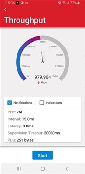 |
The throughput sample application allows you to measure the data throughput between an EFR32 device, like the BGM220P module, and another EFR32 device or a smartphone running the EFR Connect mobile app. However, the documentation fails to explain how to change any of the parameters that can affect the throughput results. No doubt some will look at the results achieved using the example's default parameters and wonder why they are getting significantly lower results than demonstrated in the animated GIF image in the documentation or as shown above in app screenshot.
In my case, my phone had something to do with it. My Android OS phone only has Bluetooth 4.2 and this does not provide a 2M PHY mode. Thankfully, my son's Samsung phone had Bluetooth 5.0 and this did allow for a 2M PHY mode.
 |  |
This helped improve throughput but it still did not give the optimum results. After further searching online, I discovered this helpful guide that enabled me to understand and resolve the issues: https://docs.silabs.com/bluetooth/latest/general/system-and-performance/throughput-with-bluetooth-low-energy-technology
Silicon Labs have a GitHub Repository (https://github.com/SiliconLabs/), which has some handy examples. It takes awhile to figure out what is applicable to our BGM220P module, but once you’ve cracked that you can take things to another level.
For example, I discovered that they had a middleware repository for NFC (https://github.com/SiliconLabs/nfc). There is source code and examples for NXP’s nt3h2x11 and for NXP’s PN71x0 type controllers.
As I had received some handy nt3h2x11 tags through a previous Project14 prize award (received the NTAG I²C plus Flex Kit), I was able to test out the nt3h2x11_i2c_read_tag example.
It was through this example, and when looking at some of the other examples on this GitHub repository, that I realised there’s a paradox when choosing to use the Simplicity Studio 5 Software Components tool to initialise drivers, and then trying to include the example code. Instead of making things easier, it makes getting your application to work more difficult than if you simply used code to initialise your components. This is particularly the case with the I2CSPM driver.
When you select to install the I2CSPM driver using the configuration tool you are asked to create an instance.
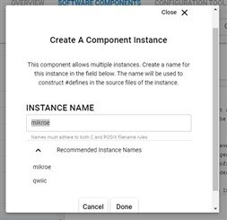
This then allows you to setup all the initialisation parameters such as Reference clock frequency, Speed Mode and your SCL and SDA pins. This then auto generates some config source code for your application and creates two other code files: sl_i2cspm_instances.h and sl_i2cspm_init.c.
The problem is, there’s not a single example available from Silicon Labs that actually uses this code architecture. So as a new learner you are left confused as to what is going on.
In my view these initialisation code files, whilst useful, actually do not save a developer much time when porting code and you tend to just copy and paste this code into your own files when creating a project from scratch. So, maybe if this code is properly incorporated into the code examples which use the Simple Button and Simple LED drivers, it will become more useful and easier to grasp.
So to create the nt3h2x11_i2c_read_tag example for the BGM220P module, all you need to do is start with the “Empty C Project” or better still the “Platform - I/O Stream USART Bare-metal” project as this includes to IO Stream drivers and work from there.
Then you just need to follow the nicely detailed instructions given in the readme: https://github.com/SiliconLabs/nfc/tree/master/examples/nt3h2x11_i2c_read_tag
As I was using the qwiic connector, I had to change the SCL and SDA ports/pins and use I2C0 for qwiic instead of I2C1, which is used by the mikroe default instance.
I also had to add in the I2C peripheral using the Software Components tool (in this case you don’t need to use the I2CSPM driver option) and of course also add in the IO Stream components as per instruction.
Then you are literally good to go. Simply build and flash your device.
Here is a very brief demo:

As we were all provided with a Mikroe Air quality 4 click, I used this click to develop for first custom application. I created a separate blog documenting my development experience: Developing a BLE Air Quality Sensor application using the BGM220 Explorer Kit

I love ePaper displays. I think they have so much potential and certainly have found their place in retail as electronic shelf labels and in public transport with electronic bus scheduled + arrival time displays etc.
I happen to have a Waveshare 2.9inch ePaper Display module. Waveshare have a wiki page, which provides technical detail, and a GitHub repository, which provides code libraries and examples for Arduino, Raspberry Pi and STM32 boards.
I downloaded the STM32 board code as this was c code and used CMSIS/HAL drivers (it turned out I did not need this part) and it looked the most compatible with Simplicity Studio 5 and our BGM220P module.
The useful code was found in the “User” folder: https://github.com/waveshare/e-Paper/tree/master/STM32/STM32-F103ZET6/User
The folders required are:
And the main code files needed are EPD2in9.h and EPD2in9.c.
The code mods required for our project are mostly within the Config folder. Here all we need to do is define our pinouts and function for our EPD breakout connector.
But first we need to define our drivers and GPIO pins within Simplicity Studio.
This is really straightforward and very quick, when using the Software Components GUI tool.
First we create our SPI driver instance using the default mikroe instance name.
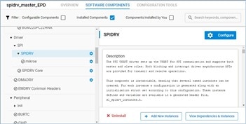
The default config settings are just fine.
It is a pity though, that you cannot disable the MISO (RX) pin using this tool, as it is not required. If you try set this to “None” you get this error:

Then we define our GPIO pins. Here I used the Platform > Peripheral > GPIO Init option.

This creates all our setup files.
Now we modify the config files to suit our purposes:
DEV_Config.h:
/*****************************************************************************
* | File          :   DEV_Config.h
* | Author      :   Waveshare team
* | Function    :   Hardware underlying interface
* | Info        :
*                Used to shield the underlying layers of each master
*                and enhance portability
*----------------
* |    This version:   V2.0
* | Date        :   2018-10-30
* | Info        :
* 1.add:
*   UBYTE\UWORD\UDOUBLE
* 2.Change:
*   EPD_RST -> EPD_RST_PIN
*   EPD_DC -> EPD_DC_PIN
*   EPD_CS -> EPD_CS_PIN
*   EPD_BUSY -> EPD_BUSY_PIN
* 3.Remote:
*   EPD_RST_1\EPD_RST_0
*   EPD_DC_1\EPD_DC_0
*   EPD_CS_1\EPD_CS_0
*   EPD_BUSY_1\EPD_BUSY_0
* 3.add:
*   #define DEV_Digital_Write(_pin, _value) bcm2835_gpio_write(_pin, _value)
*   #define DEV_Digital_Read(_pin) bcm2835_gpio_lev(_pin)
*   #define DEV_SPI_WriteByte(__value) bcm2835_spi_transfer(__value)
#
# Permission is hereby granted, free of charge, to any person obtaining a copy
# of this software and associated documnetation files (the "Software"), to deal
# in the Software without restriction, including without limitation the rights
# to use, copy, modify, merge, publish, distribute, sublicense, and/or sell
# copies of the Software, and to permit persons to  whom the Software is
# furished to do so, subject to the following conditions:
#
# The above copyright notice and this permission notice shall be included in
# all copies or substantial portions of the Software.
#
# THE SOFTWARE IS PROVIDED "AS IS", WITHOUT WARRANTY OF ANY KIND, EXPRESS OR
# IMPLIED, INCLUDING BUT NOT LIMITED TO THE WARRANTIES OF MERCHANTABILITY,
# FITNESS OR A PARTICULAR PURPOSE AND NONINFRINGEMENT. IN NO EVENT SHALL THE
# AUTHORS OR COPYRIGHT HOLDERS BE LIABLE FOR ANY CLAIM, DAMAGES OR OTHER
# LIABILITY WHETHER IN AN ACTION OF CONTRACT, TORT OR OTHERWISE, ARISING FROM,
# OUT OF OR IN CONNECTION WITH THE SOFTWARE OR THE USE OR OTHER DEALINGS IN
# THE SOFTWARE.
#
******************************************************************************/
#ifndef _DEV_CONFIG_H_
#define _DEV_CONFIG_H_

#include <stdint.h>
#include <stdio.h>
#include <stdlib.h> // malloc() free()
#include "spidrv.h"
#include "sl_spidrv_instances.h"
#include "sl_spidrv_mikroe_config.h"
#include "sl_emlib_gpio_simple_init.h"
#include "sl_emlib_gpio_init_BUSYpin_config.h"
#include "sl_emlib_gpio_init_DCpin_config.h"
#include "sl_emlib_gpio_init_RSTpin_config.h"
#include "em_gpio.h"
#include "em_cmu.h"

#include "sl_sleeptimer.h"

/**
 * data
**/
#define UBYTE   uint8_t
#define UWORD   uint16_t
#define UDOUBLE uint32_t

/**
 * e-Paper GPIO
**/
#define EPD_RST_PIN     SL_EMLIB_GPIO_INIT_RSTPIN_PORT, SL_EMLIB_GPIO_INIT_RSTPIN_PIN
#define EPD_DC_PIN      SL_EMLIB_GPIO_INIT_DCPIN_PORT, SL_EMLIB_GPIO_INIT_DCPIN_PIN
#define EPD_CS_PIN      SL_SPIDRV_MIKROE_CS_PORT, SL_SPIDRV_MIKROE_CS_PIN
#define EPD_BUSY_PIN    SL_EMLIB_GPIO_INIT_BUSYPIN_PORT, SL_EMLIB_GPIO_INIT_BUSYPIN_PIN

/**
 * GPIO read and write
**/
#define DEV_Digital_Write(_pin, _value) _value == 0 ? GPIO_PinOutClear(_pin) : GPIO_PinOutSet(_pin)
#define DEV_Digital_Read(_pin) GPIO_PinInGet(_pin)

/**
 * delay x ms
**/
#define DEV_Delay_ms(__xms) sl_sleeptimer_delay_millisecond(__xms);

void DEV_SPI_WriteByte(UBYTE value);

int DEV_Module_Init(void);
void DEV_Module_Exit(void);
#endif
DEV_Config.c:
/*****************************************************************************
* | File          :   DEV_Config.c
* | Author      :   Waveshare team
* | Function    :   Hardware underlying interface
* | Info        :
*                Used to shield the underlying layers of each master
*                and enhance portability
*----------------
* |    This version:   V2.0
* | Date        :   2018-10-30
* | Info        :
# ******************************************************************************
# Permission is hereby granted, free of charge, to any person obtaining a copy
# of this software and associated documentation files (the "Software"), to deal
# in the Software without restriction, including without limitation the rights
# to use, copy, modify, merge, publish, distribute, sublicense, and/or sell
# copies of the Software, and to permit persons to  whom the Software is
# furnished to do so, subject to the following conditions:
#
# The above copyright notice and this permission notice shall be included in
# all copies or substantial portions of the Software.
#
# THE SOFTWARE IS PROVIDED "AS IS", WITHOUT WARRANTY OF ANY KIND, EXPRESS OR
# IMPLIED, INCLUDING BUT NOT LIMITED TO THE WARRANTIES OF MERCHANTABILITY,
# FITNESS OR A PARTICULAR PURPOSE AND NONINFRINGEMENT. IN NO EVENT SHALL THE
# AUTHORS OR COPYRIGHT HOLDERS BE LIABLE FOR ANY CLAIM, DAMAGES OR OTHER
# LIABILITY WHETHER IN AN ACTION OF CONTRACT, TORT OR OTHERWISE, ARISING FROM,
# OUT OF OR IN CONNECTION WITH THE SOFTWARE OR THE USE OR OTHER DEALINGS IN
# THE SOFTWARE.
#
******************************************************************************/
#include "DEV_Config.h"

/*******************************************************************************
 *******************************   DEFINES   ***********************************
 ******************************************************************************/

// use SPI handle for EXP header (configured in project settings)
#define SPI_HANDLE                  sl_spidrv_mikroe_handle

/*******************************************************************************
 ***************************  LOCAL VARIABLES   ********************************
 ******************************************************************************/

void DEV_SPI_WriteByte(UBYTE value)
{
  // Transmission and reception buffers
  uint32_t  rx_buffer;

  Ecode_t ecode;

  // Non-blocking data transfer to slave. When complete, rx buffer
  // will be filled.
  ecode = SPIDRV_MTransferSingleItemB(SPI_HANDLE, (uint32_t)value, &rx_buffer);
  EFM_ASSERT(ecode == ECODE_OK);

}

int DEV_Module_Init(void)
{
  DEV_Digital_Write(EPD_DC_PIN, 0);
  DEV_Digital_Write(EPD_CS_PIN, 0);
  DEV_Digital_Write(EPD_RST_PIN, 1);
  return 0;
}

void DEV_Module_Exit(void)
{
    DEV_Digital_Write(EPD_DC_PIN, 0);
    DEV_Digital_Write(EPD_CS_PIN, 0);

    //close 5V
    DEV_Digital_Write(EPD_RST_PIN, 0);
}
I then modified the image data files as it contained a generic image and had images for different screen sizes.
Next step was to create my example application code, which would incorporate an init function and my “ticking” function: spidrv_app_process_action();
/***************************************************************************//**
 * @file
 * @brief spidrv master micriumos examples functions
 *******************************************************************************
 * # License
 * <b>Copyright 2020 Silicon Laboratories Inc. www.silabs.com</b>
 *******************************************************************************
 *
 * The licensor of this software is Silicon Laboratories Inc. Your use of this
 * software is governed by the terms of Silicon Labs Master Software License
 * Agreement (MSLA) available at
 * www.silabs.com/about-us/legal/master-software-license-agreement. This
 * software is distributed to you in Source Code format and is governed by the
 * sections of the MSLA applicable to Source Code.
 *
 ******************************************************************************/
#include <spidrv_waveshareepd.h>
#include <string.h>
#include <stdio.h>
#include <stdlib.h> // malloc() free()
#include "spidrv.h"
#include "sl_spidrv_instances.h"
#include "sl_emlib_gpio_simple_init.h"

#include "sl_sleeptimer.h"

#include "EPD_2in9.h"

static int EPD_2in9_test(void)
{
  printf("EPD_2IN9_test Demo\r\n");
  DEV_Module_Init();

  printf("e-Paper Init and Clear...\r\n");
  EPD_2IN9_Init(EPD_2IN9_FULL);
  EPD_2IN9_Clear();
  DEV_Delay_ms(500);

  //Create a new image cache
  UBYTE *BlackImage;
  /* you have to edit the startup_stm32fxxx.s file and set a big enough heap size */
  UWORD Imagesize = ((EPD_2IN9_WIDTH % 8 == 0)? (EPD_2IN9_WIDTH / 8 ): (EPD_2IN9_WIDTH / 8 + 1)) * EPD_2IN9_HEIGHT;
  if((BlackImage = (UBYTE *)malloc(Imagesize)) == NULL) {
      printf("Failed to apply for black memory...\r\n");
      return -1;
  }
  printf("Paint_NewImage\r\n");
  Paint_NewImage(BlackImage, EPD_2IN9_WIDTH, EPD_2IN9_HEIGHT, 270, WHITE);

#if 1   //show image for array
  printf("show image for array\r\n");
  Paint_SelectImage(BlackImage);
  Paint_Clear(WHITE);
  Paint_DrawBitMap(gImage_2in9);

  EPD_2IN9_Display(BlackImage);
  DEV_Delay_ms(2000);
#endif

#if 1   // Drawing on the image
  printf("Drawing\r\n");
  //1.Select Image
  Paint_SelectImage(BlackImage);
  Paint_Clear(WHITE);

  // 2.Drawing on the image
  printf("Drawing:BlackImage\r\n");
  Paint_DrawPoint(10, 80, BLACK, DOT_PIXEL_1X1, DOT_STYLE_DFT);
  Paint_DrawPoint(10, 90, BLACK, DOT_PIXEL_2X2, DOT_STYLE_DFT);
  Paint_DrawPoint(10, 100, BLACK, DOT_PIXEL_3X3, DOT_STYLE_DFT);

  Paint_DrawLine(20, 70, 70, 120, BLACK, DOT_PIXEL_1X1, LINE_STYLE_SOLID);
  Paint_DrawLine(70, 70, 20, 120, BLACK, DOT_PIXEL_1X1, LINE_STYLE_SOLID);

  Paint_DrawRectangle(20, 70, 70, 120, BLACK, DOT_PIXEL_1X1, DRAW_FILL_EMPTY);
  Paint_DrawRectangle(80, 70, 130, 120, BLACK, DOT_PIXEL_1X1, DRAW_FILL_FULL);

  Paint_DrawCircle(45, 95, 20, BLACK, DOT_PIXEL_1X1, DRAW_FILL_EMPTY);
  Paint_DrawCircle(105, 95, 20, WHITE, DOT_PIXEL_1X1, DRAW_FILL_FULL);

  Paint_DrawLine(85, 95, 125, 95, BLACK, DOT_PIXEL_1X1, LINE_STYLE_DOTTED);
  Paint_DrawLine(105, 75, 105, 115, BLACK, DOT_PIXEL_1X1, LINE_STYLE_DOTTED);

  Paint_DrawString_EN(10, 0, "An element 14 Road Test", &Font16, BLACK, WHITE);
  Paint_DrawString_EN(10, 20, "Hello e14 community...", &Font16, WHITE, BLACK);

  Paint_DrawNum(10, 35, 123456789, &Font12, BLACK, WHITE);
  Paint_DrawNum(10, 50, 987654321, &Font16, WHITE, BLACK);

  EPD_2IN9_Display(BlackImage);
  DEV_Delay_ms(2000);
#endif

#if 1   //Partial refresh, example shows time
  printf("Partial refresh\r\n");
  EPD_2IN9_Init(EPD_2IN9_PART);
  Paint_SelectImage(BlackImage);
  PAINT_TIME sPaint_time;
  sPaint_time.Hour = 12;
  sPaint_time.Min = 34;
  sPaint_time.Sec = 56;
  UBYTE num = 20;
  for (;;) {
      sPaint_time.Sec = sPaint_time.Sec + 1;
      if (sPaint_time.Sec == 60) {
          sPaint_time.Min = sPaint_time.Min + 1;
          sPaint_time.Sec = 0;
          if (sPaint_time.Min == 60) {
              sPaint_time.Hour =  sPaint_time.Hour + 1;
              sPaint_time.Min = 0;
              if (sPaint_time.Hour == 24) {
                  sPaint_time.Hour = 0;
                  sPaint_time.Min = 0;
                  sPaint_time.Sec = 0;
              }
          }
      }
      Paint_ClearWindows(150, 80, 150 + Font20.Width * 7, 80 + Font20.Height, WHITE);
      Paint_DrawTime(150, 80, &sPaint_time, &Font20, WHITE, BLACK);

      num = num - 1;
      if(num == 0) {
          break;
      }
      EPD_2IN9_Display(BlackImage);
      DEV_Delay_ms(500);//Analog clock 1s
  }

#endif
  printf("Clear...\r\n");
  EPD_2IN9_Init(EPD_2IN9_FULL);
  EPD_2IN9_Clear();

  printf("Goto Sleep...\r\n");
  EPD_2IN9_Sleep();
  free(BlackImage);
  BlackImage = NULL;

  // close 3V3
  printf("close 3V3, Module enters 0 power consumption ...\r\n");
  DEV_Module_Exit();

  return 0;
}


/*******************************************************************************
 **************************   GLOBAL FUNCTIONS   *******************************
 ******************************************************************************/

/*******************************************************************************
 * Initialize example.
 ******************************************************************************/
void spidrv_app_init(void)
{
  // stdout is redirected to VCOM in project configuration
  printf("Welcome to the SPIDRV example application, master mode\r\n");
  sl_spidrv_init_instances();
  sl_emlib_gpio_simple_init();
  EPD_2in9_test();
}

/***************************************************************************//**
 * Ticking function
 ******************************************************************************/
void spidrv_app_process_action(void)
{

}
These two functions are then incorporated into our standard app.c:
/***************************************************************************//**
 * @file
 * @brief Top level application functions
 *******************************************************************************
 * # License
 * <b>Copyright 2020 Silicon Laboratories Inc. www.silabs.com</b>
 *******************************************************************************
 *
 * The licensor of this software is Silicon Laboratories Inc. Your use of this
 * software is governed by the terms of Silicon Labs Master Software License
 * Agreement (MSLA) available at
 * www.silabs.com/about-us/legal/master-software-license-agreement. This
 * software is distributed to you in Source Code format and is governed by the
 * sections of the MSLA applicable to Source Code.
 *
 ******************************************************************************/
#include <spidrv_waveshareepd.h>

/***************************************************************************//**
 * Initialize application.
 ******************************************************************************/
void app_init(void)
{
  spidrv_app_init();
}

/***************************************************************************//**
 * App ticking function.
 ******************************************************************************/
void app_process_action(void)
{
  spidrv_app_process_action();
}
Then lastly, before we build our code, we need to set up our paths for our new EDP library. Here are go to properties and use the “Paths and Symbols” option:

And that is basically it.
Maybe I was “in the zone” at the time, but I found this incredibly quick and straightforward to do, compared to other IDE’s and SDK’s, once you knew Simplicity Studio 5 IDE and the default code architectures & drivers found within the SDK’s.
Here is a short demo:

When starting out with any new development board there will be hurdles to overcome as you gain familiarity with the hardware and the development environment. During this learning process you are heavily reliant on support documentation and examples (and demo software to some degree) to help built your expertise. When I compare whats on offer from Silicon Labs versus other competitors, I felt they were well short of the best in class. There was a lack of completeness and comprehensiveness on many fronts. It was for this reason that I gave 5 out of 10 for the "Demo Software was of good quality" and "Support materials were available". However, once you've broken clear from these starting-out hurdles and you understand the various libraries, and know how to navigate around some of the IDE's idiosyncrasies it then begins to prove itself.
There is still much to try out with this board, such as the mesh and the direction finding (AoA) capabilities. Now that I've got to grips with the IDE and the SDK's I'm looking forward to developing these application when time permits.
From a hardware perspective, I rather liked the BGM220P module's solder footprint. This is so much easier to use and offers more versatility for developing and then reflowing your own PCB's. However, it is a pity that the module does not break out the RF pin like what they've done for the BGM220S module.
At sub $10, the BGM220 Explorer Kit offers exceptional value and offers great versatility thanks to the different pinout configurations for click, quiic and standard 100MIL pitch. I especially liked the fact that you can connect the Explorer Kit to your computer via USB cable and use the board in Network Co-Processor (NCP) mode to develop your own desktop applications.
Thank you for reading my review.
I trust this roadtest has provided you with some clarity as to what's involved when developing applications using this wireless development board.


