element14 Community
element14 Community
    Register Log In
  • Site
  • Search
  • Log In Register
  • About Us
  • Community Hub
    Community Hub
    • What's New on element14
    • Feedback and Support
    • Benefits of Membership
    • Personal Blogs
    • Members Area
    • Achievement Levels
  • Learn
    Learn
    • Ask an Expert
    • eBooks
    • element14 presents
    • Learning Center
    • Tech Spotlight
    • STEM Academy
    • Webinars, Training and Events
    • Learning Groups
  • Technologies
    Technologies
    • 3D Printing
    • FPGA
    • Industrial Automation
    • Internet of Things
    • Power & Energy
    • Sensors
    • Technology Groups
  • Challenges & Projects
    Challenges & Projects
    • Design Challenges
    • element14 presents Projects
    • Project14
    • Arduino Projects
    • Raspberry Pi Projects
    • Project Groups
  • Products
    Products
    • Arduino
    • Avnet Boards Community
    • Dev Tools
    • Manufacturers
    • Multicomp Pro
    • Product Groups
    • Raspberry Pi
    • RoadTests & Reviews
  • Store
    Store
    • Visit Your Store
    • Choose another store...
      • Europe
      •  Austria (German)
      •  Belgium (Dutch, French)
      •  Bulgaria (Bulgarian)
      •  Czech Republic (Czech)
      •  Denmark (Danish)
      •  Estonia (Estonian)
      •  Finland (Finnish)
      •  France (French)
      •  Germany (German)
      •  Hungary (Hungarian)
      •  Ireland
      •  Israel
      •  Italy (Italian)
      •  Latvia (Latvian)
      •  
      •  Lithuania (Lithuanian)
      •  Netherlands (Dutch)
      •  Norway (Norwegian)
      •  Poland (Polish)
      •  Portugal (Portuguese)
      •  Romania (Romanian)
      •  Russia (Russian)
      •  Slovakia (Slovak)
      •  Slovenia (Slovenian)
      •  Spain (Spanish)
      •  Sweden (Swedish)
      •  Switzerland(German, French)
      •  Turkey (Turkish)
      •  United Kingdom
      • Asia Pacific
      •  Australia
      •  China
      •  Hong Kong
      •  India
      •  Korea (Korean)
      •  Malaysia
      •  New Zealand
      •  Philippines
      •  Singapore
      •  Taiwan
      •  Thailand (Thai)
      • Americas
      •  Brazil (Portuguese)
      •  Canada
      •  Mexico (Spanish)
      •  United States
      Can't find the country/region you're looking for? Visit our export site or find a local distributor.
  • Translate
  • Profile
  • Settings
3D Printing
  • Technologies
  • More
3D Printing
3D Printing Forum 3D Modelling Software Recommendations
  • Blog
  • Forum
  • Documents
  • Events
  • Polls
  • Files
  • Members
  • Mentions
  • Sub-Groups
  • Tags
  • More
  • Cancel
  • New
Join 3D Printing to participate - click to join for free!
Actions
  • Share
  • More
  • Cancel
Forum Thread Details
  • Replies 51 replies
  • Subscribers 332 subscribers
  • Views 8973 views
  • Users 0 members are here
  • 3d modeling
  • 3d cad
  • 3D Printing
  • 3d rendering
  • 3d modelling
Related

3D Modelling Software Recommendations

spannerspencer
spannerspencer over 9 years ago

Morning all!


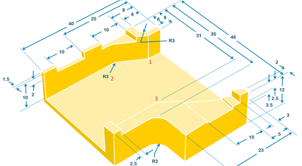
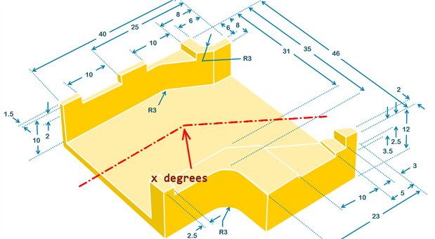
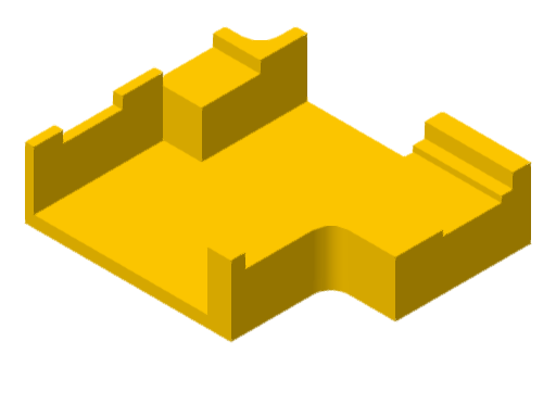
balearicdynamics has been posting some superb tweets that follow the progress of his Pi IoT design challenge, which include some great 3D models that (I assume) he then sends to the 3D printer. Is that right, Enrico?


And shabaz often makes great use of some 3D diagrams for exploded views of his amazing projects, like the HAL-CAM 9001 – Building a New Security Camera he just posted.


I've not much experience with 3D modelling software, which is my real obstacle to entry when it comes to playing with... er, I mean making use of, a 3D printer. It's not the hardware that's stopping me -- it's the software. Years about I used to dabble with Lightwave, but I was wondering what software you guys use to build your 3D models for printing (or for any other maker tasks, for that matter), and if you had any recommendations for beginners.


Maybe if you guys could sound out the popular platforms, we could then run a poll to see which ones people prefer? That being said, if you're already familiar with all the popular options, do feel free to put a poll up and we can get opinions that way, too.

  • Sign in to reply
  • Cancel

Top Replies

  • shabaz
    shabaz over 9 years ago +6
    Hi Spanner, I don't use any 3D modelling software currently, so I'm curious too to find out what gets used with 3D-printers. (I don't own one yet). I'm a heavy user of graphics programs (Paint shop, Inkscape…
  • Jan Cumps
    Jan Cumps over 9 years ago in reply to spannerspencer +5
    Spanner Spencer wrote: ... There's definitely a lot of scope there! ...
  • beacon_dave
    beacon_dave over 9 years ago +4
    I'm currently using Nemetschek Vectorworks for 3D modelling. Vectorworks, Inc. | BIM & CAD Design Software It's not oriented specifically toward 3D printing, but it can export to STL file format for 3D…
Parents
  • shabaz
    shabaz over 9 years ago

    Hi Spanner,


    I don't use any 3D modelling software currently, so I'm curious too to find out what gets used with 3D-printers.

    (I don't own one yet).

    I'm a heavy user of graphics programs (Paint shop, Inkscape etc), so all my 3D renderings are not to scale : )

    and so I cannot do camera movements around the object etc, since they are all flat 2D with no modelling data.

    At school we learned manual drafting from someone who did this once for a living, so I like isometric views and

    orthographic projections!

    I use PowerPoint to get most of it composed, create shadow and shadings, etc - not the best tool since it isn't designed

    for it, but I'm a power-user of it now! I also like Jan Cumps pencil renderings!

    To get a rough idea of proportionality, I make use of the 'size' settings for objects in powerpoint, and

    a calculator. Sometimes even placing a ruler on the screen : ) It's not so bad, it works.


    Here's an example, drawn up in PowerPoint, so these are just graphical lines, no 3D objects at all.

    image

    Final result:

    image

    • Cancel
    • Vote Up +6 Vote Down
    • Sign in to reply
    • Cancel
  • beacon_dave
    beacon_dave over 9 years ago in reply to shabaz

    Really nice but I think we are still missing a few dimensions to work with on the 3D printer here  image


    • The top diagonal face - both end points
    • The lower diagonal face - the end point in the centre
    • The thickness of the base is unclear as well - looks like it could be 2mm but ambiguous
    • Cancel
    • Vote Up 0 Vote Down
    • Sign in to reply
    • Cancel
  • balearicdynamics
    balearicdynamics over 9 years ago in reply to beacon_dave

    Dave,

    checking with attention, you can see that all the dimensions are shown directly or indirectly. The only mistake is the thickness of the base while all the other information if not directly quoted can be deducted. This is a technique used in all the quoted designs to avoid too many quotes. Personally I find this method of the indirect quoting a bit complex to read but I am aware that this keep the design clean.


    Enrico

    • Cancel
    • Vote Up 0 Vote Down
    • Sign in to reply
    • Cancel
  • beacon_dave
    beacon_dave over 9 years ago in reply to balearicdynamics

    Enrico,


    Struggling with points 1, 2 & 3 even with attention. image


    Point 1 - is 8 from the top edge but I don't see a measurement from the left or right edge. Looks to be less than 6 from the right edge though.

    Point 2 - there is no centre for the radius of the fillet to get a tangent for the edge of the diagonal face.

    Point 3 - is 31 from the top edge but I don't see a measurement from either the left or right edge. Looks to be less than 23 and greater than 15 from the right edge though.


    image

    • Cancel
    • Vote Up +1 Vote Down
    • Sign in to reply
    • Cancel
  • balearicdynamics
    balearicdynamics over 9 years ago in reply to beacon_dave

    Hello Dave,

    This is an almost complex piece and quotes are not easy to deduct.


    1. Here you have a 8x8 square (view from top) and inside a 6x6 square. So the internal straight line connect the two sides of the square intersecting at 6 and 6. CAD usually gives this option to close with a straight line a surface (that then will be extruded) deciding the intersection points.
    2. These radius didn't need center. The reason is that these are not circles but arcs. Usually in CAD you should have several options to design arcs, in this case the ideal option in my opinion is arc by radius and two point. You set the first and second edge (that is exactly 90 degrees of an arc) and set the radius, then the CAD add the needed calculations.
    3. If you refer in this case to the internal straight line, the procedure is the same as in point 1. If you refer to potentially missing measures, the approach is the same: the internal part is 31  over a total length of 46 by one side and some calculation on the other side.

    The parts that seems not correct are automatically generated as the arc is fixed and the total length is shown on the other side.


    The issue in this design is that there are some wrong proportions respect the sizes to if you make a real object with these measures maybe you have some surprises. Remain the fact that designing with a CAD program it is sure extremely easier to generate with less measures but using relative reference points (e.g. intersections. Take in account that it is best practice with this kind of objects to create easy sub objects then joining them and applying boolean operations like element subtraction.


    BTW maybe I am not so clear due my language difficulties.


    Enrico

    • Cancel
    • Vote Up +1 Vote Down
    • Sign in to reply
    • Cancel
  • shabaz
    shabaz over 9 years ago in reply to beacon_dave

    Hi Dave!


    You could be right, its a limitation of doing it manually, I could miss bits.

    Whereas a 3D modelling system would not construct the shapes unless all

    parameters were present, and then they can be used for generating the documentation (I'm guessing).


    Its a bit messy labelling all on a single isometric to be honest. But its the view most people recognise (probably orthographic projections are less familiar unless people are from an engineering background).

    • Cancel
    • Vote Up 0 Vote Down
    • Sign in to reply
    • Cancel
  • kulky64
    kulky64 over 9 years ago in reply to beacon_dave

    beacon_dave is right about all 3 points. They are ambiguous.

    • Cancel
    • Vote Up +1 Vote Down
    • Sign in to reply
    • Cancel
  • shabaz
    shabaz over 9 years ago in reply to kulky64

    Hi!


    I don't doubt there could be missing measurements, (by the way this is a duct part, we expect duct area to be approximately consistent through the part).


    Actually I believe we could fix it with a single value (e.g. x degrees) and either text, or a center line. I'm not 100% sure this is valid on an isometric, but for an orthographic it would be.


    For example:

    image


    The center line or text would indicate that duct property we desire, i.e. parallel lines inside.

    We already know the duct inside is 31-1.5 = 29.5mm.  And we know where the lower-rightmost leg of the duct is placed, because it is marked as 2mm. So this would result in all measurements being defined.


    The thickness of the part is not implied, it is given, you can see the 12mm measurement marked at the right side of the diagram, and 10mm marked on the left side of the diagram.


    I agree with Enrico, I don't believe any more is needed on the radii. Ordinarily that would 'naturally' occur if your tooling was of the same radius. I'm guessing when you do that in a CAD package, it would internally compute it the same way.

    • Cancel
    • Vote Up +2 Vote Down
    • Sign in to reply
    • Cancel
  • beacon_dave
    beacon_dave over 9 years ago in reply to balearicdynamics

    Hi Enrico,


    I can follow your language 95% of the time image


    Point 1 - I think this is still ambiguous as to my eye it looks less than 6.

    I've sketched in the 8 and the 6 boxes which shows the right vertical edge of the diagonal plane doesn't line up with a projection of the 6.


    image


    Point 2 - you don't need the centre of the arc but you would need to know the placement of the two lines it joins. Currently I don't appear to have that information without knowing the angle of intersection of the two duct channels as Shabaz later points out.


    Point 3 - I still only see a measurement on one axis there. As with point 1 it looks a bit ambiguous.


    Out of curiosity I was in the process of creating a 3D model of the same part to generate an isometric view from 3D to see how it line up with  Shabaz' 2D drawing...


    I got this far in about 5mins:

    imageimage

    • Cancel
    • Vote Up +2 Vote Down
    • Sign in to reply
    • Cancel
  • beacon_dave
    beacon_dave over 9 years ago in reply to shabaz

    Hi Shabaz,


    Yes the angle 'x degrees' would work for me image


    The base thickness is a little ambiguous in my opinion as there is nothing to say that the upper and lower walls of the duct are actually the same height.


    The fillet radii are fine as long as we know the angle of the intersection of the duct. CAD as you say will do it automatically. In Vectorworks for example you can just select the two lines and specify the radius and the fillet is inserted in-between them.

    • Cancel
    • Vote Up +1 Vote Down
    • Sign in to reply
    • Cancel
  • balearicdynamics
    balearicdynamics over 9 years ago in reply to beacon_dave

    Hello Dave!


    you are smart if you understand 95% of my language... I have some difficulties to the technical english especially in drawing terms as I am not English mother tongue. As far as I see you have done a great job from the information of the Shabaz' design. I think that as a hand-drawn design there are some incorrectness but almost inside a good tolerance. Remain the fact that using a CAD it is impossible to made mistakes like missing quotes.

    Well done in my opinion. What software did you used?


    Enrico

    • Cancel
    • Vote Up +1 Vote Down
    • Sign in to reply
    • Cancel
Reply
  • balearicdynamics
    balearicdynamics over 9 years ago in reply to beacon_dave

    Hello Dave!


    you are smart if you understand 95% of my language... I have some difficulties to the technical english especially in drawing terms as I am not English mother tongue. As far as I see you have done a great job from the information of the Shabaz' design. I think that as a hand-drawn design there are some incorrectness but almost inside a good tolerance. Remain the fact that using a CAD it is impossible to made mistakes like missing quotes.

    Well done in my opinion. What software did you used?


    Enrico

    • Cancel
    • Vote Up +1 Vote Down
    • Sign in to reply
    • Cancel
Children
  • beacon_dave
    beacon_dave over 9 years ago in reply to balearicdynamics

    Enrico,


    I use Nemetschek Vectorworks Designer + Renderworks

    Gallery | Vectorworks


    I mainly use it for venue modelling purposes as it supports 3D rendering of video projection, lighting etc. However it also appears to work fine for generating STL output for 3D printing.


    I started out with early versions of AutoCAD for mechanical, OrCAD for schematic, and Wintek smArtworks for PCB  around 28 years ago and have used various packages since depending upon employer and job roles since.

    • Cancel
    • Vote Up +1 Vote Down
    • Sign in to reply
    • Cancel
  • balearicdynamics
    balearicdynamics over 9 years ago in reply to beacon_dave

    Hi Dave!

    It seems that spannerspencer has centred the target with this discussion. There is a so large number of replies that I missed your answer.


    Thank you for the specifications. Me too I started working with Autocad 1 in the mid of '80 and never stopped ... But this Vectorworks sounds interesting. I have used for a while the Dassault CAD suite but it is too oriented to the CAM machinery. For now I am stabilised on Rhino that is a good balance between performances and easy design. With some important missed features like camera motion.


    Enrico

    • Cancel
    • Vote Up +1 Vote Down
    • Sign in to reply
    • Cancel
element14 Community

element14 is the first online community specifically for engineers. Connect with your peers and get expert answers to your questions.

  • Members
  • Learn
  • Technologies
  • Challenges & Projects
  • Products
  • Store
  • About Us
  • Feedback & Support
  • FAQs
  • Terms of Use
  • Privacy Policy
  • Legal and Copyright Notices
  • Sitemap
  • Cookies

An Avnet Company © 2025 Premier Farnell Limited. All Rights Reserved.

Premier Farnell Ltd, registered in England and Wales (no 00876412), registered office: Farnell House, Forge Lane, Leeds LS12 2NE.

ICP 备案号 10220084.

Follow element14

  • X
  • Facebook
  • linkedin
  • YouTube