I've never used a 555 timer as a monostable, so I thought I'd give it a go. This should be easy,
shouldn't it.
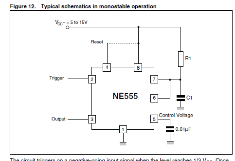
Here's the circuit as it's given on an old ST datasheet.

As they describe it, a falling edge at the trigger input sets the output and releases the capacitor
to start charging. When it gets to the internal threshold voltage, the output is reset and the
capacitor is discharged ready for another go. I've wired one up on a breadboard with a 10uF and 22k
for the timing capacitor and resistor. According to the timing formula (t=1.1*C*R) that should give
me an output pulse width of something like 240ms, though using an electrolytic means it won't be
all that accurate.
To give the falling edge, I've also wired up another 555 (no expense spared when it comes to e14
blogging) as an astable. That way I can see how the monostable behaves when repetitively triggered.
The astable period is around 1.5 seconds.
What I expected was a nice neat positive-going pulse at every falling edge of the astable waveform.
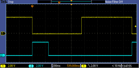
What I got was this
The yellow trace is the trigger input to the monostable and the blue is the output. The pulse
period is ok, but after that it can't seem to make up its mind what it wants to do. Evidently,
there's more to this than the ST datasheet would lead me to believe.
Looking at the capacitor voltage, I see this
The capacitor does charge, but then just sits there without the reset happening. The reset doesn't
happen until the input goes high again, so it looks like the trigger needs to be not only a
negative-going edge but also short enough that it doesn't block the reset of the monostable.
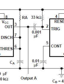
The old National datasheet for the NE555 explains this better and, in a suggested circuit for a
chain of monostables, shows the use of a coupling capacitor and a pull-up resistor (1nF and 33k) as
a differentiator for the trigger as a way to to get the necessary short pulse width. (There's no
sign of a diode, to catch the positive-going edge that will ascend from the rail voltage, so
presumably they're confident that the anti-static protection diode can cope.)

So, here it is with the extra capacitor and resistor added

That's better. Just for interest, here's the differentiator output as the trigger input sees it.
That gives a pulse width that's around 10us at the trigger input.
Finally, for fun, I've wired a chain of five monostables in a row, with the outputs driving LEDs.
Here they are pulsing in sequence every time that the astable triggers them:
In case it's not obvious, the astable is on the right and the chain of monostables run from right to left. Why I did it like that I don't know, but I'm not going to change it now.
If you found this interesting and would like to see more blogs I've written, a list can be found
here: /members-area/b/blog/posts/jc2048-blog-index-new-version
References
[1] https://www.st.com/en/clocks-and-timers/ne555.html
[2] https://www.ti.com/lit/ds/symlink/ne555.pdf

-

robogary
-
Cancel
-
Vote Up
0
Vote Down
-
-
Sign in to reply
-
More
-
Cancel
Comment-

robogary
-
Cancel
-
Vote Up
0
Vote Down
-
-
Sign in to reply
-
More
-
Cancel
Children