


A very simple HET example: Project0 - generate a PWM signal with a fixed duty cycle.
The previous posts were a showcase: let the timer module do some calculations while generating and and measuring signals. In this much simpler post let's take a step back. The TI Application Note NHET Get Started*1 shows the core specialty of the HET module: counting |
In order to create a fixed frequency pulse with a fixed duty cycle, only two lines of PWM code are needed:
L00: CNT{next = L01, reg = A, max = 624}
L01   MCMP { next=L00,hr_lr=HIGH,en_pin_action=ON,pin=6,order=REG_GE_DATA,action=PULSEHI,reg=A,data=0x1D4,hr_data=0x00};
The first one, CNT, is a Counter to 624. It generates the frequency.
The second instruction, MCMP, is a compare. It generates the duty cycle.

source: TI document SPU490 Enhanced High-End Timer (NHET) Assembler User's Guide
Let's have a look at the problem statement and some calculations first (translated to a different clock and different output signal requirements from the NHET Get Started application note)
given:
- Main system clock HCLK = 110 MHz
asked (what do we want to achieve as putput signal?):
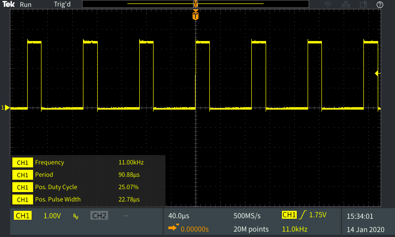
- PWM frequency = 11 kHz
- PWM duty cycle dc = 25%
- PWM accuracy = 150 ns steps or better
Calculate the HET Clock Settings
First, I need to calculate what frequency is needed to drive the precision of 150 ns.
This is a function of the High Resolution clock.
That clock is 110 MHz by default, good for an 9.091 ns (1/110 MHz) accuracy.
-> VCLK2 = 110 MHz
We can achieve a precision of 150 with a 6.667 MHz clock (1/150 ns).
To derive an approx 6.667 MHz clock, we can divide our 110 Mhz by 16.
This gives 6.875 MHz, better than the minimum req of 6.667 to get the precision.
Note that we can only get frequencies by dividing the 110 MHz clock using the HR (high-resolution divide ratio).
The result is that we'll have a better than 150 ns (145.455 ns) even if we divide the clock by 16.
takeaway: the slowest HET high-resolution clock that allows us to give an accuracy of 150 ns (or better) is 6.875 MHz. That's 110 MHz / 16.
-> hr = 16
Second, let's see how to set the loop resolution pre-scaler.
As seen at the start of the blog, we need to be able to run 2 instructions. Both instructions take 1 cycle.
The number of available timeslots (cycles) is lr * hr.
We need 2 cycles, and the number of available cycles is lr * hr.
lr = 2/hr= 2/16. That allows us to set the lowest setting, 1, to have enough calculation time
-> lr = 1
source: TI document RM46x 16/32-Bit RISC Flash Microcontroller Technical Reference Manual - PFR register
the number of timeslots is lr * hr.
-> ts = 16 * 1 = 16
With that, the high resolution and loop resolution period can be calculated:
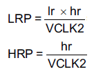
-> LRP = 16 * 1 / 110 MHz = 0.0000001454545 = 145.45 ns
-> HRP = 1/110 MHz = 0.00000000909 = 9.09 ns
Configure the HET Program to Generate the Desired PWM Signal with these Timings
PWM frequency is driven by the first line of code, the Count instruction.
The duty cycle is controlled by the second line, the Compare instruction.
To achieve a frequency of 11 MHz, we have to calculate how many counts it takes to achieve the goal.
-> Signal Period = 1 / 11 MHz = 90.90909 µs
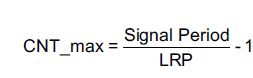
-> CNT_max = (90.90909 µs / 145.45 ns) - 1 = 624
You can see that in line 1 of the HET code:
L00: CNT{next = L01, reg = A, max = 624}
To achieve a duty cycle of 25%, we need to calculate the compare value for the Compare instruction.
-> dc = 0.25
The MCMP instruction can be configured to set the pin to a logic 1 when the compare matches a virtual counter value.
With a duty cycle requirement of 25% the number of hr cycles =

-> PWM_duty = ((624 + 1) × 1) × (1 – 0.25) = 468
Now comes a tricky part  - check Application Note SPRABA0B - NHET Getting Started (link in the post header) for a full explanation.
I can't do it better and don't want to copy the whole section.
In essence:
The MCMP instruction's compare value exists of 2 pieces of data, named hr_data and data.

You have to fit the number 468 in that.
Depending on the lr setting, you have a number of bits of that 468 that 'll fit in the hr_data. The rest has to go into data.
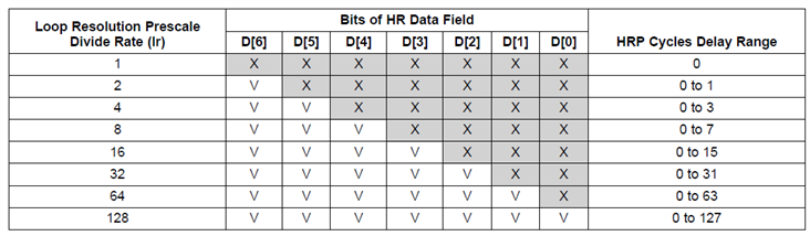
Our lr is 1, so we don't have access to the hr_data. So we have to skip the whole 6 bits of hr_data.
468 = 111010100b
left shifted by 6 bits: 111010100000000b
The right 6 bits ( 6 LSBs) (I know this is silly, but in the TI app note they have an example where the lr = 8, so that explains it better because they will have hr_data bits) have to go to hr_data:
hr_data = 000000b = 0x00
The remaining bits (all MSBs exept the 6 LSBs) go to data: 111010100b = 0x1D4
This gives the 2nd line of HET code:
L01 MCMP { next=L00,hr_lr=HIGH,en_pin_action=ON,pin=6,order=REG_GE_DATA,action=PULSEHI,reg=A,data=0x1D4,hr_data=0x00};
The result is the PWM signal shown in the post header: 11 kHz, 25% duty cycle.
As you can see, even for the simplest of examples, you need to use your brain - and get used to the mechanisms.
To make things somewhat more confusing, a hr of 16 and a lr of 1 are configured like this in HALCoGen :
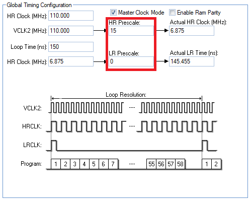
This is because they represent the values as explained in the technical reference manual for the PFR register:
    /** - Setup prescaler values
    *     - Loop resolution prescaler
    *     - High resolution prescaler
    */
    hetREG1->PFR = (uint32)((uint32) 0U << 8U)
                | ((uint32) 15U);
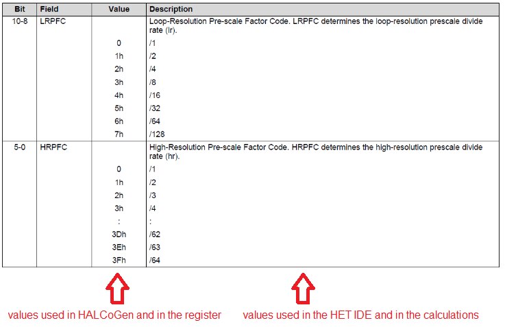
You have to use the translation table from that manual (see above, I've copied the relevant parts called LRPFC and HRPFC) to get the values that are to be used in the calculations.
In the HET IDE, the same prescalers are configured so:
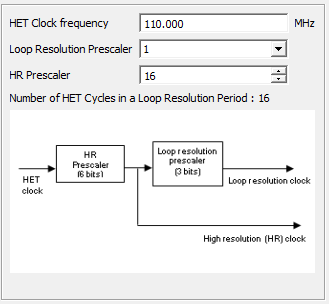
These are the translated values. I hope that by writing this down here, I never ever have to look this up again in the manuals and code.
A lot to learn and remember ...
| Acronym | Description |
CNT_max CNTHCLK hr High hr_data HRP lr LRP PWM ts VCLK2 | Maximum counter value of virtual count instruction Main system clock resolution divide ratio High resolution data field of an instruction High resolution period Loop-resolution divide ratio Loop-resolution period duty PWM duty cycle Timeslots Peripheral clock used as master clock for NHET |
The project is attached to this post. It includes the Code Composer Studio, HET and HALCoGen projects. Enjoy!
*1: Not available from TI USA anymore - this is a backup from TI Japan. If you have a link to a good TI application note, better download it. They are disappearing from their website regularly, also for active components and designs. Their wiki site, containing labs and errata that have never been moved to official documentation, is slanted for removal. I think their e2e community (as a forum to discuss, not a support forum) and the LaunchPad initiative are all but dead. Don't know what's going on there but it looks like they gave up on the maker community as a gateway for future customers. |
| Related Blog |
|---|
| 1: adapt TI example to a LaunchPad |
| 2: Generate Dynamic Duty Cycle |
| 3: Measure a PWM Signal and HET Interrupts |
| 4: Getting Started |
| 5: Getting Started with the Wave Form Simulator |
Top Comments