element14 Community
element14 Community
    Register Log In
  • Site
  • Search
  • Log In Register
  • About Us
  • Community Hub
    Community Hub
    • What's New on element14
    • Feedback and Support
    • Benefits of Membership
    • Personal Blogs
    • Members Area
    • Achievement Levels
  • Learn
    Learn
    • Ask an Expert
    • eBooks
    • element14 presents
    • Learning Center
    • Tech Spotlight
    • STEM Academy
    • Webinars, Training and Events
    • Learning Groups
  • Technologies
    Technologies
    • 3D Printing
    • FPGA
    • Industrial Automation
    • Internet of Things
    • Power & Energy
    • Sensors
    • Technology Groups
  • Challenges & Projects
    Challenges & Projects
    • Design Challenges
    • element14 presents Projects
    • Project14
    • Arduino Projects
    • Raspberry Pi Projects
    • Project Groups
  • Products
    Products
    • Arduino
    • Avnet Boards Community
    • Dev Tools
    • Manufacturers
    • Multicomp Pro
    • Product Groups
    • Raspberry Pi
    • RoadTests & Reviews
  • Store
    Store
    • Visit Your Store
    • Choose another store...
      • Europe
      •  Austria (German)
      •  Belgium (Dutch, French)
      •  Bulgaria (Bulgarian)
      •  Czech Republic (Czech)
      •  Denmark (Danish)
      •  Estonia (Estonian)
      •  Finland (Finnish)
      •  France (French)
      •  Germany (German)
      •  Hungary (Hungarian)
      •  Ireland
      •  Israel
      •  Italy (Italian)
      •  Latvia (Latvian)
      •  
      •  Lithuania (Lithuanian)
      •  Netherlands (Dutch)
      •  Norway (Norwegian)
      •  Poland (Polish)
      •  Portugal (Portuguese)
      •  Romania (Romanian)
      •  Russia (Russian)
      •  Slovakia (Slovak)
      •  Slovenia (Slovenian)
      •  Spain (Spanish)
      •  Sweden (Swedish)
      •  Switzerland(German, French)
      •  Turkey (Turkish)
      •  United Kingdom
      • Asia Pacific
      •  Australia
      •  China
      •  Hong Kong
      •  India
      •  Korea (Korean)
      •  Malaysia
      •  New Zealand
      •  Philippines
      •  Singapore
      •  Taiwan
      •  Thailand (Thai)
      • Americas
      •  Brazil (Portuguese)
      •  Canada
      •  Mexico (Spanish)
      •  United States
      Can't find the country/region you're looking for? Visit our export site or find a local distributor.
  • Translate
  • Profile
  • Settings
Connector Technology & Design
  • Technologies
  • More
Connector Technology & Design
Forum Identifying a Connector or at least Manufacturer
  • Blog
  • Forum
  • Documents
  • Quiz
  • Events
  • Polls
  • Files
  • Members
  • Mentions
  • Sub-Groups
  • Tags
  • More
  • Cancel
  • New
Join Connector Technology & Design to participate - click to join for free!
Actions
  • Share
  • More
  • Cancel
Forum Thread Details
  • State Suggested Answer
  • Replies 5 replies
  • Answers 1 answer
  • Subscribers 128 subscribers
  • Views 1327 views
  • Users 0 members are here
  • connector
  • nes
  • nintendo
  • unknown
Related

Identifying a Connector or at least Manufacturer

Former Member
Former Member over 9 years ago

I am looking to build a board that will be installed in an original NES. With the right connectors I will be able to build this such that no changes are needed to the console in order to add a small feature, but I need to find the existing connectors in order to source compatible new ones. Luckily, one of the connectors I want to use was identifiable(after a lot of searching/learning) as one of the JST variations: all the measurements match the datasheets nicely, and so do the visuals.


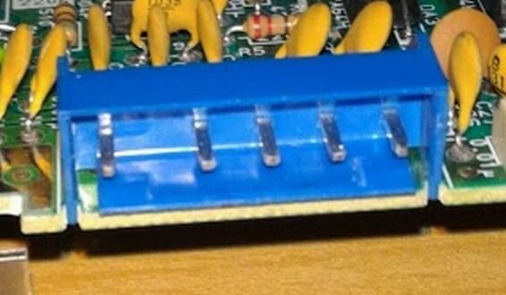
The other connector is more of a problem: P6. It is used to connect to the power/reset/LED board mounted to the front of the case, and I cannot figure out who even makes it. Pictures of the connector and logo are below.


I've tried asking this in the NES hardware forums online, but no luck yet.


I'm also open to more suggestions on where to look.


Info I have:

- 5 pins - keyed with pin 1 at 1.5 times other pitch

- pitch from pin 1 to pin 2 = 7.5mm

- pitch for all other pins = 5 mm

- connector is between 6 mm and 6.5 mm high

- connector is between 27.3 mm and 27.7 mm wide

- connector is about 4.2 mm deep

- pins are about 1.1 mm square

- blue( a lighter blue, but as with anything like this, it varies a bit between batches and with age )

(measurements are approximate, my digital calipers are a bit cheap, sometimes randomly adding exactly 1/5th of an inch to measurements - these are double and sanity checked)


There is no manufacturer name on either part, just a single letter('P') and a circular symbol that kinda looks like a 6 sided star, divided into 6 segments in a ring. This symbol is also found on one of my NES systems on the power and reset switches, still no company name. Other NES have Mitsumi switches, but they don't seem to be the same company. This would have been manufactured in the millions in the 80's, so there must be a datasheet somewhere.


Let me know if any other information will help.


Image of the logo: https://goo.gl/photos/Gc2213oZm1ZmzDyz6

Image of connector: https://goo.gl/photos/kNJjqzAKBSNs338Y7

Left is pin 1.


Thanks for any help or direction.

G42

  • Sign in to reply
  • Cancel

Top Replies

  • dougw
    dougw over 9 years ago +1
    Looks like a job for a 3D printer...
  • shabaz
    0 shabaz over 9 years ago

    Hi Jared,


    It could be custom, at least the outer connectors on most Nintendo hardware had custom connectors for the controllers etc.

    Since 7.5mm and 5mm are exact multiples of 2.5, perhaps there is a 2.5mm or 2.54mm connector that could mate, with some of the sockets in the connector not making contact. I've not seen anything though that I could say for sure could fit. You'd have to keep trawling various connector manufacturer websites if you wanted to try to find something that could fit but wasn't designed for it.

    The manufacturer may have been Japanese and perhaps didn't sell in other countries at that time, and long stopped making it since this hardware is so old. All speculation though.

    As another option you could consider locating individual receptacles that would fit the 1.1mm pins, connect wires to them and heat-shrink around for insulation. Fiddly, but it is an option. Something like this basically: https://www.mill-max.com/products/rec/0760

    You'd have to contact them for information, and you may need to buy a thousand of them or so, they might not sell in smaller quantities.

    • Cancel
    • Vote Up 0 Vote Down
    • Sign in to reply
    • Verify Answer
    • Reject Answer
    • Cancel
  • dougw
    0 dougw over 9 years ago

    Looks like a job for a 3D printer...

    image

    • Cancel
    • Vote Up +1 Vote Down
    • Sign in to reply
    • Verify Answer
    • Cancel
  • Former Member
    0 Former Member over 9 years ago in reply to dougw

    Now that's something for me to acquire. I do wonder if I could find one that can do the shape well though. Some of the walls involved at 0.75mm, I might see if I can find out if there are printers that could do that. I'm still hoping to identify a compatible pre-existing one(Molex has something close) and save me a lot of work for a toy project.

    • Cancel
    • Vote Up 0 Vote Down
    • Sign in to reply
    • Verify Answer
    • Cancel
  • Former Member
    0 Former Member over 9 years ago in reply to shabaz

    It looks like there may be a Molex connector that has the same spacing, but the plastic housings appear incompatible from the datasheet. I had not looked at 2.5mm spacing connectors though, and that could be an interesting avenue. If I could find even single row headers with that spacing and for the larger pins it would probably work.


    Oddly enough, the connectors that run to the two front controller ports from the main board(visible in white in the picture) are just JST-PH 7 pin (I've ordered some to confirm, but all the measurements match the datasheet and visually).


    I figure if I can find out the manufacturer who used that logo, I can probably get who owns them today and if they still make them.


    More digging will need to happen. It's the only empty piece of info in my documentation of the main board, and that annoys me enough to put more time then it's worth into it.

    • Cancel
    • Vote Up 0 Vote Down
    • Sign in to reply
    • Verify Answer
    • Cancel
  • dougw
    0 dougw over 9 years ago in reply to Former Member

    To get the odd spacing you can pull one pin out of the Molex and drill a new hole for it - make sure the hole is very tight fit.

    • Cancel
    • Vote Up 0 Vote Down
    • Sign in to reply
    • Verify Answer
    • Cancel
element14 Community

element14 is the first online community specifically for engineers. Connect with your peers and get expert answers to your questions.

  • Members
  • Learn
  • Technologies
  • Challenges & Projects
  • Products
  • Store
  • About Us
  • Feedback & Support
  • FAQs
  • Terms of Use
  • Privacy Policy
  • Legal and Copyright Notices
  • Sitemap
  • Cookies

An Avnet Company © 2025 Premier Farnell Limited. All Rights Reserved.

Premier Farnell Ltd, registered in England and Wales (no 00876412), registered office: Farnell House, Forge Lane, Leeds LS12 2NE.

ICP 备案号 10220084.

Follow element14

  • X
  • Facebook
  • linkedin
  • YouTube