element14 Community
element14 Community
    Register Log In
  • Site
  • Search
  • Log In Register
  • Community Hub
    Community Hub
    • What's New on element14
    • Feedback and Support
    • Benefits of Membership
    • Personal Blogs
    • Members Area
    • Achievement Levels
  • Learn
    Learn
    • Ask an Expert
    • eBooks
    • element14 presents
    • Learning Center
    • Tech Spotlight
    • STEM Academy
    • Webinars, Training and Events
    • Learning Groups
  • Technologies
    Technologies
    • 3D Printing
    • FPGA
    • Industrial Automation
    • Internet of Things
    • Power & Energy
    • Sensors
    • Technology Groups
  • Challenges & Projects
    Challenges & Projects
    • Design Challenges
    • element14 presents Projects
    • Project14
    • Arduino Projects
    • Raspberry Pi Projects
    • Project Groups
  • Products
    Products
    • Arduino
    • Avnet & Tria Boards Community
    • Dev Tools
    • Manufacturers
    • Multicomp Pro
    • Product Groups
    • Raspberry Pi
    • RoadTests & Reviews
  • About Us
  • Store
    Store
    • Visit Your Store
    • Choose another store...
      • Europe
      •  Austria (German)
      •  Belgium (Dutch, French)
      •  Bulgaria (Bulgarian)
      •  Czech Republic (Czech)
      •  Denmark (Danish)
      •  Estonia (Estonian)
      •  Finland (Finnish)
      •  France (French)
      •  Germany (German)
      •  Hungary (Hungarian)
      •  Ireland
      •  Israel
      •  Italy (Italian)
      •  Latvia (Latvian)
      •  
      •  Lithuania (Lithuanian)
      •  Netherlands (Dutch)
      •  Norway (Norwegian)
      •  Poland (Polish)
      •  Portugal (Portuguese)
      •  Romania (Romanian)
      •  Russia (Russian)
      •  Slovakia (Slovak)
      •  Slovenia (Slovenian)
      •  Spain (Spanish)
      •  Sweden (Swedish)
      •  Switzerland(German, French)
      •  Turkey (Turkish)
      •  United Kingdom
      • Asia Pacific
      •  Australia
      •  China
      •  Hong Kong
      •  India
      •  Korea (Korean)
      •  Malaysia
      •  New Zealand
      •  Philippines
      •  Singapore
      •  Taiwan
      •  Thailand (Thai)
      • Americas
      •  Brazil (Portuguese)
      •  Canada
      •  Mexico (Spanish)
      •  United States
      Can't find the country/region you're looking for? Visit our export site or find a local distributor.
  • Translate
  • Profile
  • Settings
Connector Technology & Design
  • Technologies
  • More
Connector Technology & Design
Forum How can i test RS-485
  • Blog
  • Forum
  • Documents
  • Quiz
  • Events
  • Polls
  • Files
  • Members
  • Mentions
  • Sub-Groups
  • Tags
  • More
  • Cancel
  • New
Join Connector Technology & Design to participate - click to join for free!
Actions
  • Share
  • More
  • Cancel
Forum Thread Details
  • Replies 43 replies
  • Subscribers 127 subscribers
  • Views 10622 views
  • Users 0 members are here
  • connector
  • wiring
  • communication
Related

How can i test RS-485

Dsoky
Dsoky over 2 years ago

Hello, i am looking for a way to test MAX-485 , i do not have any idea how to do it , anyone can help me?

  • Sign in to reply
  • Cancel

Top Replies

  • beacon_dave
    beacon_dave over 2 years ago in reply to Dsoky +2
    Perhaps Jan Axelson's book 'Serial Port Complete' might help you ? http://janaxelson.com/spc.htm It covers the basics of serial communications, covers working with RS485 networks, and includes some…
  • KennyMillar
    KennyMillar over 2 years ago in reply to Dsoky +2
    Yeah no problem, here it is: https://www.analog.com/media/jp/technical-documentation/data-sheets/1111.pdf If you have any questions please feel free to ask - I use these chips in loads of things. …
  • Dsoky
    Dsoky over 2 years ago in reply to KennyMillar +2
    Ok good stuff i found that module https://handsontec.com/index.php/product/ft232r-usb-to-serialttl-converter-module/ will that work ?
  • Dsoky
    Dsoky over 2 years ago in reply to javagoza

    i see that useful thanks, what i want to do is to test if the ic is wotking or not, I am a maintenence engineer and for devices that have communication fault we cant be so sure if that ic (MAX458) for example is faulty , an so i am looking for a way to test the ic itself.

    • Cancel
    • Vote Up 0 Vote Down
    • Sign in to reply
    • Cancel
  • Jan Cumps
    Jan Cumps over 2 years ago in reply to Dsoky

    Ow. In that case I'd build a little testbed. The cheapest would most likely be 2 arduinos, one arduino CAN shield, and one custom little test-jig that you create to put the IC-under-test on. Test firmware already exists

    • Cancel
    • Vote Up 0 Vote Down
    • Sign in to reply
    • Cancel
  • javagoza
    javagoza over 2 years ago in reply to Dsoky

    So I think you can go for a simple circuit to test the chips on their receive and transmit functions.

    See datasheet

    image

    • Cancel
    • Vote Up 0 Vote Down
    • Sign in to reply
    • Cancel
  • beacon_dave
    beacon_dave over 2 years ago in reply to Dsoky

    Perhaps Jan Axelson's book 'Serial Port Complete' might help you ?

    http://janaxelson.com/spc.htm 

    It covers the basics of serial communications, covers working with RS485 networks, and includes some programming.

    Another useful reference might be this e-Book 'A Practical Guide to Using RS-422 and RS-485 Serial Interfaces'

    https://advantech-bb.com/wp-content/uploads/2014/12/RS-422-RS-485-eBook.pdf

    • Cancel
    • Vote Up +2 Vote Down
    • Sign in to reply
    • Cancel
  • Dsoky
    Dsoky over 2 years ago in reply to beacon_dave

    Thanks a lot!.

    • Cancel
    • Vote Up 0 Vote Down
    • Sign in to reply
    • Cancel
  • KennyMillar
    KennyMillar over 2 years ago in reply to Dsoky

    Yeah no problem, here it is:https://www.analog.com/media/jp/technical-documentation/data-sheets/1111.pdf

    If you have any questions please feel free to ask - I use these chips in loads of things.

    Also here's a diagram showing how to wire it up.
    The double-s symbol means "long bit of wire"

    image

    and the A wire and B Wire should be a twisted pair.

    • Cancel
    • Vote Up +2 Vote Down
    • Sign in to reply
    • Cancel
  • KennyMillar
    KennyMillar over 2 years ago in reply to KennyMillar

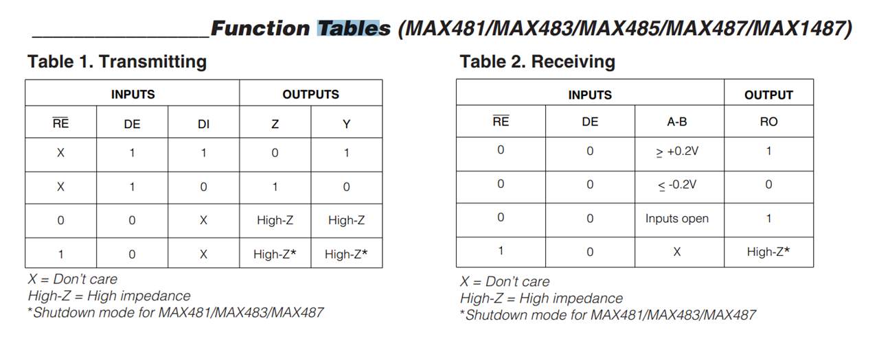
    Oh.. and there's one more thing...
    You only need to connect 1 GPIO pin to DE and !RE - because DE is active-high and RE is active low, it means you can connect them both to the same pin. When you drive the pin HIGH you have a trasnmitter, when you drive the pin LOW you have a receiver ;-)

    • Cancel
    • Vote Up 0 Vote Down
    • Sign in to reply
    • Cancel
  • Dsoky
    Dsoky over 2 years ago in reply to KennyMillar

    Thanks for that, i keep studying about that topic every day for some hours and now i know the concept but still idk how to add the ic  itself , i want to start only with two ics to test them.

    What am trying to say is how to communicate between an pc and pc using the ic , what is the connections and the wiring , what is the code or the procedures, all that i still dont know about , but the concept of RS-485 know i understand what it does,

    The main point now is how to insert data to DI what do i need for that?

    And also how to receive data from RO like how can i show the data coming out of this pin, what do i need to show these data? so i can compare it with the data i sent on DI (which idk yet how to do that) to ensure if the ic is working well or not.

    • Cancel
    • Vote Up 0 Vote Down
    • Sign in to reply
    • Cancel
  • KennyMillar
    KennyMillar over 2 years ago in reply to Dsoky

    Ah yeah - ok, so connecting a chip like this to a PC is not as easy as yuo might think.
    That's because a PC does not have any GPIO pins, like an Arduino does, or a Raspberry PI.

    So what you'd need is another chip first - which has USB and can be programmed to be a "CDC" device.
    Such a chip might be the FT232R from FTDI
    That will give you TX, RX pins, and a number of other programmable pins such as CTR, DTR, RTS, CTS - you are then able to use one of these as the DE/RE control. Then you can use any kind of serial terminal on a PC to send and receive via RS485.

    The datasheet for THAT chip is at https://ftdichip.com/wp-content/uploads/2020/08/DS_FT232R.pdf and it includes (section 7.2) a schematic on how to make a PC to RS485 convertor! The chip which they call "SP481" in the example, could be replaced with a MAX485 as it has the same pinout.

    • Cancel
    • Vote Up +1 Vote Down
    • Sign in to reply
    • Cancel
  • Dsoky
    Dsoky over 2 years ago in reply to KennyMillar

    Ok that will help a lot thanks, i will study that and will tell you about the news. Grin

    • Cancel
    • Vote Up 0 Vote Down
    • Sign in to reply
    • Cancel
<>
element14 Community

element14 is the first online community specifically for engineers. Connect with your peers and get expert answers to your questions.

  • Members
  • Learn
  • Technologies
  • Challenges & Projects
  • Products
  • Store
  • About Us
  • Feedback & Support
  • FAQs
  • Terms of Use
  • Privacy Policy
  • Legal and Copyright Notices
  • Sitemap
  • Cookies

An Avnet Company © 2025 Premier Farnell Limited. All Rights Reserved.

Premier Farnell Ltd, registered in England and Wales (no 00876412), registered office: Farnell House, Forge Lane, Leeds LS12 2NE.

ICP 备案号 10220084.

Follow element14

  • X
  • Facebook
  • linkedin
  • YouTube