


Texas Instrument's GUI Composer can be used to design with LCD displays. But it also has a useful API for the MSPM0: JSON communication over UART. This is a low footprint mechanism where you can exchange data with a PC GUI, or with another device.
What does the JSON GUI layer offer?
It's a ready-to-use framework, with formatter, parser and callbacks. JSON is a lightweight data format. It doesn't require a lot of cpu time to format data to it. And the structure doesn't add a lot overhead to the data size.
The GUI has all that's needed to register data that you want to exchange with another party. And it does the job of preparing the data for sending, and extracting it when receiving.
Upon receiving of data, it will invoke the callback function that you developed for that particular attribute. It supports an interrupt based application. You can send data based on a timer interrupt, and a UART RX interrupt calls the JSON parser when data is sent by your counterpart.
Example:
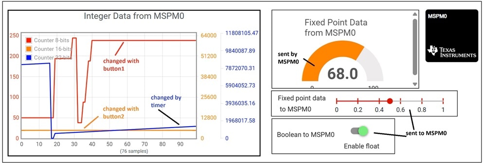
In this demo, when you click on the green button on the PC GUI, a JSON message is sent to your EasyL1105 over UART. This will result that the function below will be called. Your firmware state is kept in sync with the GUI controls.
// Global variables for the callbacks
volatile bool bEnableSwitch;
volatile _q qIncrement;

// ***** Application Callback Functions to Process data *****
void callback_boolEnable(char* string)
{
    // Example to receive a boolean
    bEnableSwitch = GUIComm_ReadBool(string);
}
The other way around, if you click a button on the EasyL1105, the red or orange line (depending on which button you pressed) in the PC GUI graph will change.
The Demo (and why it's better than TI's original  )
)
The GUI composer framework brings the
- proposed setup for the UART and TIMER
- interrupt handler implementation for UART rx
- data registry mechanism
- JSON formatter and parser
- callbacks support
- superloop data send example
On the PC side, the GUI that's running is also made with GUI composer. It's TI's standard GUI composer for JSON example for many LaunchPads. I didn't change it.
First; code registers the callbacks for the data points we'll be receiving. And sends default values to the PC GUI
const tGUI_RxCmd GUI_RXCommands[] = {
    {"bEnable", callback_boolEnable},
    {"u16Data", callback_QMathData},
};

// ...

int main() {

    // ...

    /* Initialize GUI layer */
    GUI_Init();

    /* Initialize the RX command callbacks */
    GUI_InitRxCmd(&GUI_RXCommands[0],
        (sizeof(GUI_RXCommands) / sizeof(GUI_RXCommands[0])));

    // ...

    /* Send default value of variables */
    GUIComm_sendUInt8("c1", STR_LEN_TWO, u8Counter);
    GUIComm_sendUInt16("c2", STR_LEN_TWO, u16Counter);
    GUIComm_sendUInt32("c3", STR_LEN_TWO, u32Counter);
    GUIComm_sendInt16("c4", STR_LEN_TWO, (int16_t) qCounter);
    GUIComm_sendInt16("u16Data", STR_LEN_SEVEN, (int16_t) qIncrement);
    GUIComm_sendBool("bEnable", STR_LEN_SEVEN, bEnableSwitch);

    /* Wait for ACK from GUI */
    __WFI();
The (low power savvy!) superloop will exchange data only if we have the green button on the PC GUI set on:
    while (1) {
        /* Send updates to GUI when there is a periodic timer interrupt */
        while (bUpdateGUI == true) {
            GUIComm_sendUInt8("c1", STR_LEN_TWO, u8Counter);
            GUIComm_sendUInt16("c2", STR_LEN_TWO, u16Counter);
            GUIComm_sendUInt32("c3", STR_LEN_TWO, u32Counter);
            if (bEnableSwitch == true) {
                GUIComm_sendInt16("c4", STR_LEN_TWO, (int16_t) qCounter);
            }

            bUpdateGUI = false;
        }

        if (bUpdateGUI == false) {
            __WFE();
        }
    }
The _WFI() allows the ARM to go in lower power mode while waiting for interrupt. _WFE() makes it loop in low power mode.
There's more happening in the demo. A GPIO and TIMER interrupt, that change the data shown in the graph - and also tells the superloop to send data. And that UART rx interrupt that will kick of the JSON parser and call the relevant callbacks. All code is attached.
Why is my port better than TI's original? Glad you ask.
TI's example is available for many LaunchPads. Although it's initially written with SysConfig, they disabled its code generation mechanism and made controller specific changes outside the SysConfig generated files. I've undone that.
- re-enabled file generation, and the option to change between controllers and packages with SysConfig
- culled all peripheral setup code that was outside the framework.
- killed the bespoke linker script
- removed custom startup code.
This means that you can now change pins, ports, timer and UART settings as usual. And if you have a different controller or package, you can migrate to that one with the Switch wizard of SYsConfig..I've used it to change the controller on the MSPM0L1117 LaunchPad (where Iborrowed the demo example from) to the 28 pin MSPM0L1105 on the EasyL1105. To change the UART pins. And to select different GPIOs for the two buttons that interact with the PC GUI graphs.
The readme file in the project has a link to the PC GUI. It runs in your browser, and uses TI Cloud Agent to connect to your board's COM port. If you don't have the agent installed, the GUI will ask you to do that.
Alternatively, you can connect a terminal with 9600 8N1, and see the JSON data coming from the EasyL1105. If you're a hero, you can even send a JSON package to it, and see if you can make it call one of the two callbacks ...
The example project for CCS is attached. Check the SysConfig file to learn what pins are used (and adapt them if needed): gc_simple_json_EasyL1105_20251016.zip


