


|
shabaz designed a development kit for the recent Texas Instruments MSPM0 microcontroller series. In this post, I document them (mainly as a reminder for @self
|

Some of the changes will be available in Rev2 of the PCB. Others, I've done for a specific design.
1: UART RXD pin
This modification will be an option in Rev2.
UART RXD uses PA18. This is shared with the bootloader invoke. It's not easy to balance the bootloader pulldown, and the internal TX pull-up of the CH340K.
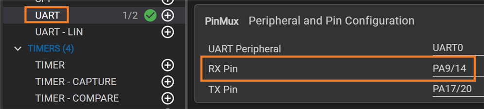
This resulted in the board not starting up with the UART RX jumpers of J3 placed (= use USB for UART). I switched to PA9 for UART RX.
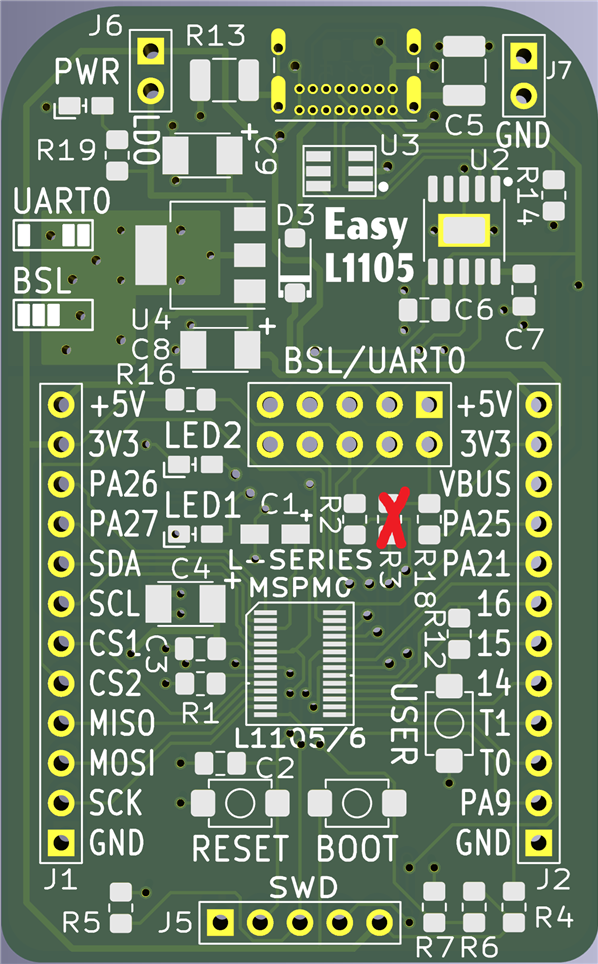
top side changes:
- remove R3, but keep it handy
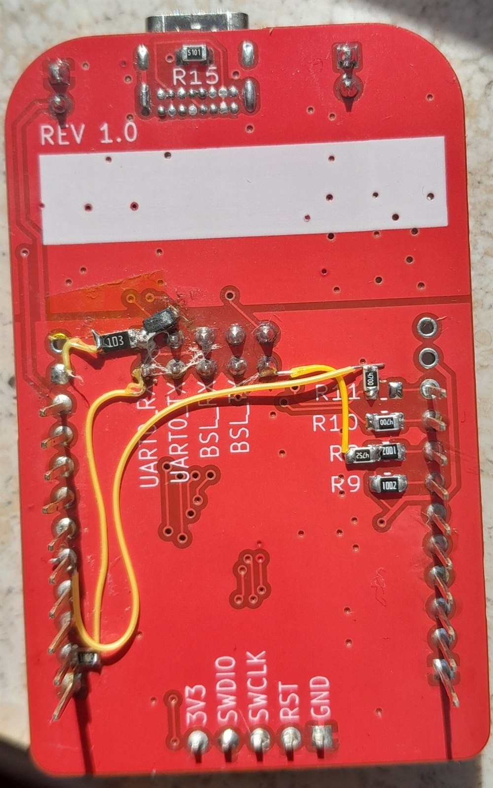
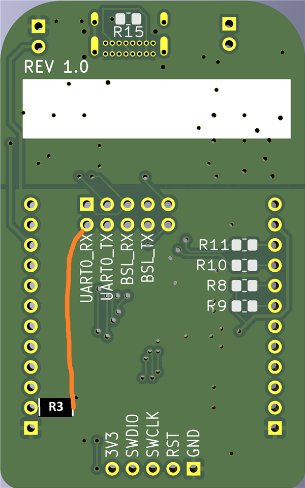
bottom side changes:
- solder the saved R3 to PA9 (J2.2)
- solder a bodge wire between the other side of the resistor, and J3.2 (where it then can be connected to the UART IC via a jumper)
SysConfig
2: UART RXD pull-up.
This modification will be available in Rev2.
This is a must do if you do mod 1. Advised if you don't do that mod.
The USB IC pulls its TX to 5V when idle. On the MSPM0, this results into voltages above the 3.6V maximum. The modification pulls that signal (closer) to the3.3V rail.
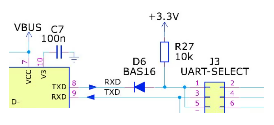
image source: Rev2 schematic of shabaz
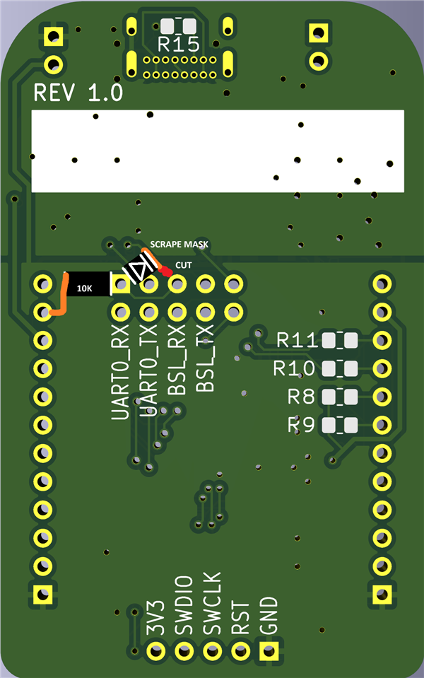
bottom side changes:
- with an exacto knife, cut the small trace from J3.1 to a via, as close to the J3 pin as you can
- scrape the solder mask carefully off the remainder of that trace, up to where it meets the ground plane.
- I put capton tape on the area above J3, from pin 1 to almost the trace that we just scraped.
- solder a 10K resistor to J3.1
- solder a bodge wire from the other side of the resistor to a J2.2 (3V3)
- solder the anode of a diode to the same J3.1. Ideally, something like an SMD 1N4148, that fits between the pin and the scaped trace
- solder the cathode of that diode to the trace you just scraped the mask off.

No SysConfig changes
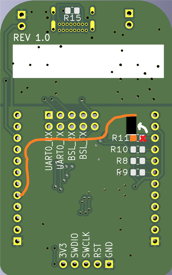
Blue LED not on analogue pin
This is for my own project.
I want to use the internal opamp (GPAMP), and only PA26 can be used as the non-inverting input. The LED circuit that's attached to the pin interferes with it. I'm rerouting the blue LED functionality to the less exciting PA14
bottom side changes:
- desolder R11
- solder it back, 90° turned, to its left pad (next to the label)
- solder a bodge wire between the other side of the resistor, and J2.5 (PA14)
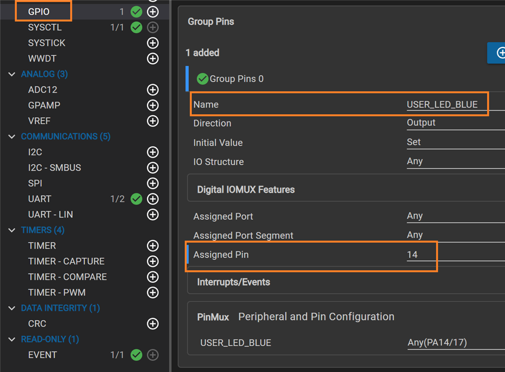
SysConfig
*RST pull-up
This modification will be available in Rev2.
It's a necessary change. Detected by shabaz during the initial tests, and documented in EasyL1105: A Dev Board for the TI ARM Cortex-M0+ L-Series .
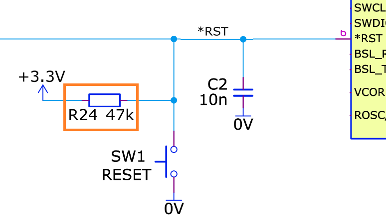
image source: Rev2 schematic of shabaz
bottom side changes:
- solder a 4K7 resistor to the left side of R8 (next to the label)
- solder a bodge wire from the other side of the resistor to J3.10 (*RST).
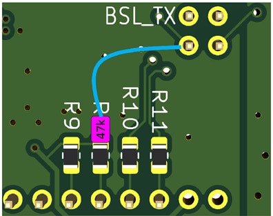
image source: kit intro blog post by shabaz
No SysConfig changes
Thanks for reading. Happy experimenting!


