I'm trying to generate a complementary PWM wave, with dead time, with a timer of a RX23E-A microcontroller. This signal will later be used to create an excitor signal for precision measurements.
I have an evaluation board from Road test: Renesas Solution Starter Kit for RX23E-A. It has options for USB, CAN and RS-485/profibus. Out of box, it doesn't expose a timer. But it has the capabilities to do so. This blog shows a few modifications I did to get at 4 signals of timer MTU2a (Multi-function timerpulse unit 2).
| This post is similar to Renesas Solution Starter Kit for RX23E-A - break out the SPI signals , but for a different peripheral, and a different connector. Mainly for my own documentation, if I want to revert later. |
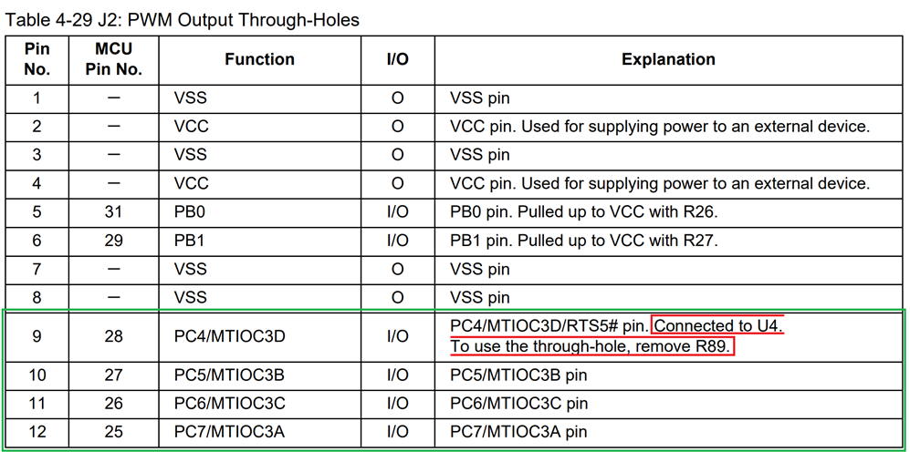
The application note for this kit shows what I can get at without bodge wires. The connector J2 exposes a number of PWM lines. Including ones for channel MTU3 of the MTU2a peripheral. But one of them is connected to the timer and profibus ICs. So I need to do just a little change.


On the PCB, I need to mount J2, and remove R89. The resistor is tiny. Luckily, there is a lot of empty space around it. It's easy to remove.

It turned out to be very easy. I used a hot air pencil this time, and blew R89 off its pads.
J2 is a standard pin header. Again, there was enough room to solder it in without difficulties.
I taped the resistor on the piece of paper that already had the ones for my SPI mod, and put it back inside the kit's box. In case I want to restore it to its original configuration.
Here's the result:

